



Search News
Industry Portal
Popular Tags
How Vacuum Insulated Cryogenic Engineering Reduces Boil-Off and Heat Leak
Author
Time
Click Count
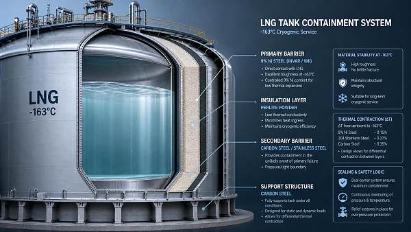
Vacuum insulated cryogenic engineering is evaluated first by one hard metric: how effectively it slows heat ingress into a fluid that must remain at deep-cryogenic temperature. In LNG service, liquid temperature is typically around -163°C, so even a small increase in heat leak can raise vapor generation, disturb pressure management, and force the system to spend energy handling boil-off gas rather than preserving cargo condition. The insulation system therefore has to be judged as a thermal barrier, a structural assembly, and a long-duration sealing problem at the same time.
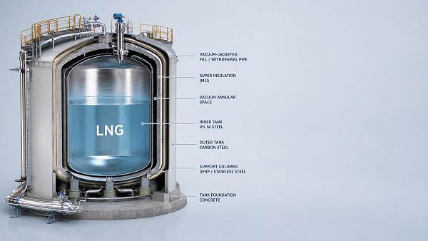
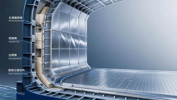
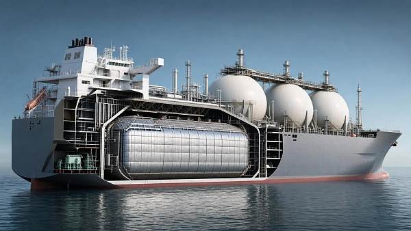
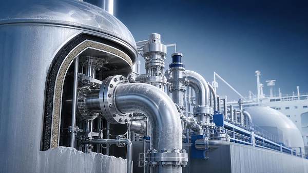
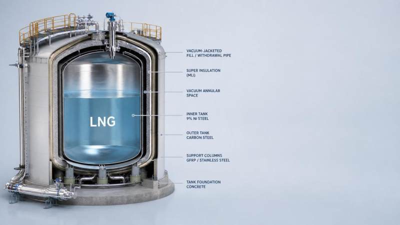
Heat reaches a cryogenic vessel by conduction, convection, and radiation. Vacuum insulation is used because it suppresses gaseous conduction and natural convection inside the annular space. Once most gas molecules are removed, the remaining thermal path is dominated by solid bridges such as support members, piping penetrations, instrumentation stems, and radiation exchange between warmer and colder surfaces. That is why vacuum insulated cryogenic engineering never depends on vacuum alone. It works only when the vacuum space, support geometry, surface finish, and multilayer insulation are designed as one integrated thermal system.
Where boil-off begins in real equipment
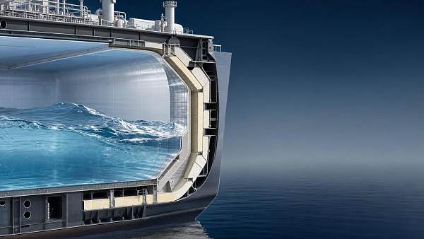
Boil-off is often discussed as if it were generated uniformly across the tank wall. In practice, local thermal weak points matter disproportionately. A well-insulated shell can still show avoidable vapor formation if there are poorly isolated saddles, stiffener attachments, valve boxes, pump tower interfaces, or unoptimized nozzle necks. In transport and marine systems, these discontinuities become more important because the equipment also sees vibration, sloshing loads, hull or skid movement, and repeated temperature cycling. Thermal design that looks acceptable on a static drawing may perform differently once fabrication tolerances, welding distortion, and field supports are included.
A technical review normally separates the heat leak problem into two layers. The first is the bulk performance of the insulated envelope. The second is the collection of concentrated thermal bridges that bypass that envelope. The second layer is where many specification misunderstandings occur. A supplier may present insulation thickness and vacuum level clearly, while the largest avoidable losses are hidden in support details, penetrations, or installation practices that were treated as secondary.
Why the vacuum space matters beyond pressure value
A low pressure in the annular space reduces the number of gas molecules available to carry heat. However, the absolute pressure reading by itself does not fully describe insulation quality. Residual gas composition, outgassing rate, leak tightness over time, and the cleanliness of internal surfaces all affect long-term performance. Moisture, hydrocarbons, or trapped contaminants can desorb slowly after evacuation, degrading the vacuum and increasing heat transfer even when the initial commissioning value looked acceptable.
For that reason, vacuum insulated cryogenic engineering typically includes more than a single evacuation step. Internal surfaces may need cleaning, drying, and controlled handling before closure. Bake-out or warm nitrogen purging may be used in some manufacturing routes to reduce adsorbed moisture. Getter materials or cryopumping effects can help under certain conditions, but they do not compensate for poor fabrication discipline. If weld porosity, elastomer incompatibility, or contaminated insulation layers are present, the vacuum space may drift out of its intended regime during service.
The geometry of the vacuum annulus also influences behavior. Narrow spaces can reduce volume to be evacuated, but they may complicate multilayer insulation placement and increase the chance of accidental compression. Larger annular spaces may make installation easier, yet they increase enclosure size and can demand tighter control of support alignment. There is no universal optimum without reference to vessel size, hold time requirement, allowable mass, and service motion.
Multilayer insulation reduces radiation, but only if it is installed correctly
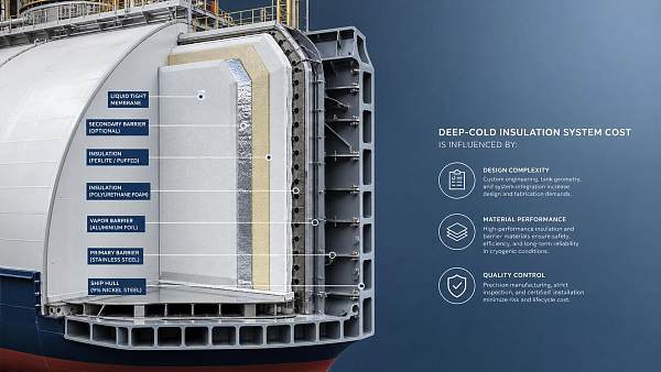
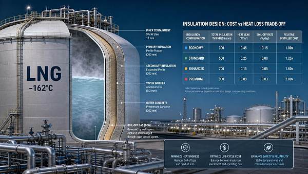
Once convective and gaseous conductive heat transfer are suppressed, radiation becomes a larger fraction of the remaining heat leak. Multilayer insulation, often formed from alternating low-emissivity reflective foils and spacer materials, is used to interrupt radiative exchange between the warm outer boundary and the cold inner vessel. Aluminumized films are common in many cryogenic assemblies, although the exact layer materials and separator choices vary with temperature range, mechanical handling, and contamination sensitivity.
Performance depends heavily on layer density and compression control. If the blanket is packed too tightly, solid conduction rises because the contact area between layers increases. If it is too loose, the layer count per unit thickness may become inconsistent and create gaps or settling zones. Sharp edges, weld spatter, burrs, and careless routing around supports can puncture reflective films or collapse spacing. In field discussions, multilayer insulation is sometimes treated like a passive wrapping material; in reality it behaves more like a precision thermal component.
Another common error is assuming nominal layer count equals actual thermal resistance. The installed condition matters more than the drawing note. Overlapping seams, circumferential joints, access around nozzles, and behavior under transport vibration can all alter effective performance. For marine containment-related service, where movement is persistent rather than occasional, retention methods for insulation layers deserve close attention because migration or compaction over time can create warm spots.
Supports are usually the dominant solid heat bridge
The inner vessel has to be held in position while staying cold, and the outer shell stays near ambient conditions. Every support between them becomes a conductive path. Material choice therefore has structural and thermal consequences at once. Austenitic stainless steels are often selected in cryogenic service for toughness retention at low temperature, but they still conduct more heat than ideal insulation materials. Glass-fiber-reinforced composites or other low-conductivity structural elements may be used in some support locations where load case, fire philosophy, and fabrication method permit. The final arrangement often combines metallic load paths with thermal breaks or extended conduction length to limit heat leak.
Length-to-cross-section ratio matters. A short, thick support will generally pass more heat than a longer, slender element made from a suitable material, assuming both meet mechanical requirements. Yet simply making supports thinner is not a free improvement. Buckling resistance, shock loads, fatigue under vibration, thermal contraction mismatch, and manufacturing repeatability all impose limits. The engineering question is therefore not whether the support is thermally efficient in isolation, but whether it remains dimensionally stable and inspectable throughout cooldown, steady operation, warm-up, and repeated service cycles.
Support junctions deserve close review during drawing assessment. Heat may bypass an intended thermal break through fasteners, backup plates, instrumentation clamps, or secondary brackets added late in fabrication. These additions are often small in mass and easy to overlook, but they can create concentrated cold spots on the outer structure or elevate vapor generation locally at the inner wall.
Penetrations, valves, and piping often define practical performance
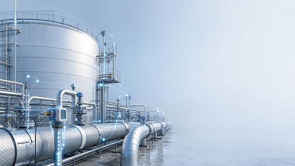
Nozzle design is one of the least forgiving parts of a cryogenic system. Fill lines, withdrawal lines, pressure build-up circuits, level instrumentation, safety relief paths, and pump penetrations all interrupt the insulated boundary. Each penetration has to satisfy process, mechanical, and maintainability requirements while keeping heat leak under control. Long nozzle necks, vacuum-jacketed lines, thermal intercepts, and carefully arranged standoff distances are all used to reduce unwanted energy transfer.
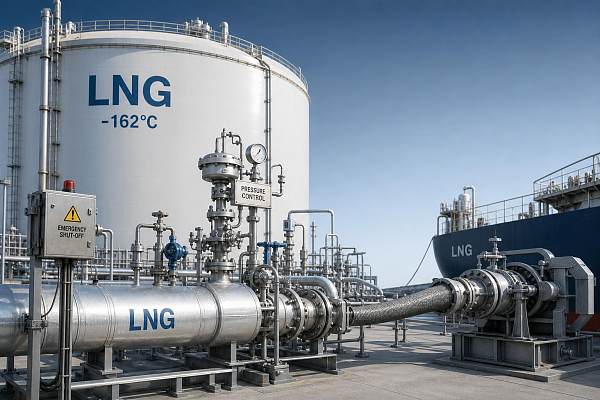
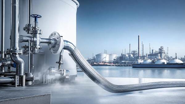
Vacuum-jacketed piping can be highly effective where line runs are long or where product recirculation cannot tolerate flashing. However, performance depends on field handling. Misalignment, support over-constraint, rough lifting, or local denting of the outer jacket can affect annular integrity or insulation condition. During transport and installation, the external shell of a vacuum-jacketed line may look cosmetically acceptable while internal spacers or bellows have already been stressed. Acceptance should therefore go beyond appearance and include vacuum verification and, where specified, hold-time or thermal performance checks.
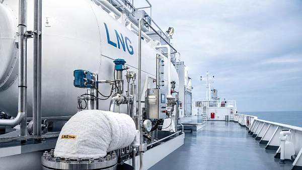
Valves introduce an additional complication because they combine metallic mass, stem leakage paths, and maintenance access. Extended bonnet designs are often used to keep packing at a warmer zone while protecting the cryogenic fluid boundary, but the bonnet itself still becomes a conduction path. If valve location forces frequent exposure to warm ambient air, frost patterns around the body or bonnet can indicate local heat ingress or insulation discontinuity. Frost alone is not a full diagnostic, yet it is often a useful visual signal that should not be dismissed as normal decoration of cold equipment.
Boil-off control is linked to pressure management, not just insulation thickness
Reducing heat leak lowers the vapor generation rate, but boil-off behavior also depends on tank pressure strategy, liquid level, filling ratio, and operational cycling. A partially filled tank can present more vapor space and different wall wetting behavior than a full tank, which may alter how heat input converts into pressure rise. Stratification can complicate interpretation further. If warmer layers form in the liquid or vapor zones, measured pressure change may not map neatly to a simple insulation calculation.
This matters when comparing specifications. A quoted hold time, evaporation rate, or standby duration is meaningful only if the boundary conditions are stated clearly enough: ambient temperature range, initial fill condition, pressure limits, line isolation status, and whether attached components such as vaporizers or economizer circuits are included in the thermal balance. Without those details, two systems can appear comparable on paper while reflecting different test assumptions.
Fabrication discipline often decides whether the design survives into service
Many heat-leak problems begin long before the tank is cooled down. Welding procedures can distort annular geometry and create contact points that were absent in the model. Surface contamination can remain trapped behind insulation layers. Inadequate drying before final closure can leave residual moisture that later degrades vacuum quality. If evacuation ports, gauges, and seals are positioned mainly for shop convenience rather than future verification, the equipment may become difficult to monitor once installed.
Material handling is equally important. Reflective films can tear, powder insulation can settle, and support components can be nicked or bent during assembly. Some damage remains hidden after outer shell closure. That is why witness points around pre-close inspection are often more valuable than relying only on final vacuum readings. A stable vacuum after evacuation is necessary, but it does not prove that internal insulation placement is uniform or that all support clearances remain as intended.
Transport from workshop to site can also change the outcome. Road shock, lifting at incorrect points, prolonged exposure to humid air before commissioning, or incomplete re-evacuation after installation may all alter performance. Large marine or industrial modules with cryogenic sections are especially sensitive because pipework, supports, and structural steel from adjacent systems can impose loads on insulated components after the original factory alignment is complete.
Maintenance is largely about preserving the original thermal assumptions
Vacuum insulated systems are sometimes treated as low-maintenance because the insulation is enclosed. The enclosure, however, can hide slow degradation. Vacuum loss may develop gradually through seal aging, microleaks, or repeated thermal cycling at instrument penetrations. Outer shell temperature mapping, pressure trend monitoring in the annulus where applicable, and observation of changing frost or condensation patterns can provide early warning before cargo losses or process instability become obvious.
When a vacuum space has to be opened for repair, restoration quality matters. Reassembly with substitute spacers, mixed insulation materials, or uncontrolled cleanliness can leave the system technically closed but thermally inferior. Likewise, replacement valves or instruments with different stem lengths, body mass, or support arrangements may alter local heat ingress even if process connections are dimensionally compatible.
One practical misunderstanding is to focus only on the coldest components. Warm-end attachments can be just as important because they anchor the conductive path. Cable trays, guards, access platforms, and retrofit brackets added near cryogenic nozzles may appear harmless from a process standpoint while increasing thermal bridging or constraining movement during contraction.
Application conditions change the preferred insulation balance
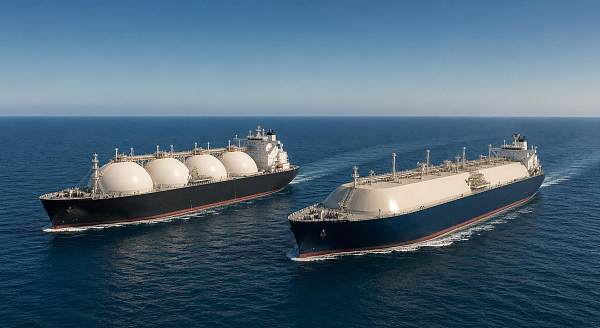
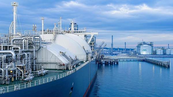
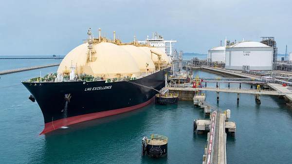
Stationary industrial storage, road transport units, laboratory dewars, and LNG marine systems all use the same thermal principles, but the design balance shifts with service conditions. A stationary vessel may prioritize long hold time and easy vacuum monitoring. A transport vessel may accept a different geometry to manage mass, shock resistance, and regulatory envelope constraints. Marine service adds persistent motion, salt-laden atmosphere on external surfaces, and integration with cargo handling systems that may introduce numerous penetrations and structural interfaces.
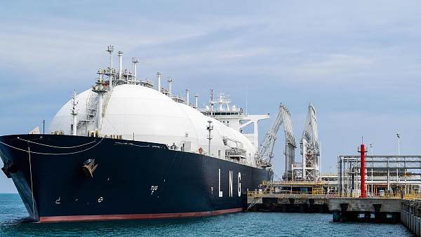
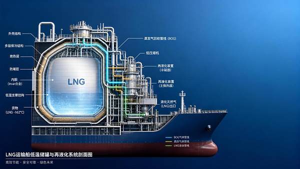
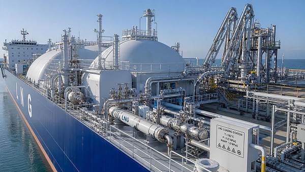
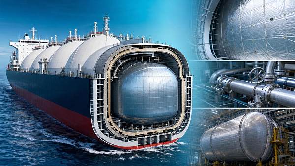
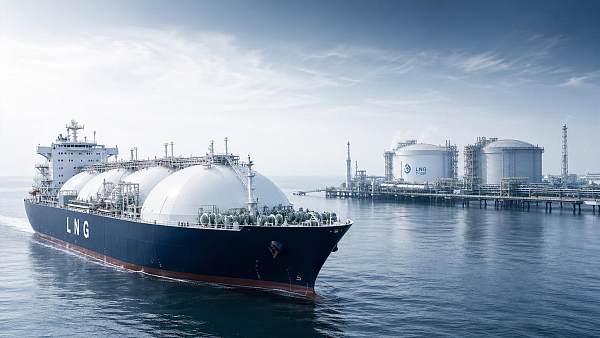
For LNG carriers and related cryogenic installations, thermal evaluation should account for the whole route the heat can take, not only the nominal insulation package. Inner vessel supports, suspended pump structures, dome regions, line connections, and transition pieces between cargo containment and handling equipment often govern practical performance. Vacuum insulated cryogenic engineering reduces boil-off most effectively when those interfaces are treated as first-order thermal features rather than accessories.
If the assembly maintains vacuum integrity, preserves multilayer insulation condition, minimizes conductive bridges, and keeps penetrations thermally disciplined, boil-off reduction follows from the physics rather than from a nominal thickness value. Where one of those elements is weak, the system may still pass a specification sheet review while carrying unnecessary heat leak into service.
Recommended News
 Sep 28, 2026When is nickel steel containment needed for cryogenic storage?Nickel steel containment is essential when cryogenic tanks face brittle-fracture risk. Discover how temperature, loads, and tank design guide the right choice.
 Sep 11, 2026How membrane containment systems demonstrate compliance with IMO standardsMembrane containment systems IMO standards: discover how LNG carriers prove compliance through verified barriers, testing, monitoring, and traceable records.
 Sep 10, 2026How membrane and Moss containment systems differ for LNG carriersLNG cargo containment for carriers: compare membrane and Moss systems for capacity, BOG, safety, sloshing, lifecycle cost, and operational flexibility.
 Sep 03, 2026What drives membrane containment systems cost in LNG projects?Membrane containment systems cost depends on tank design, materials, labor, QA, and boil-off performance. Discover how to control LNG project risk and lifecycle costs.
 Aug 11, 2026How Vacuum Insulated Cryogenic Engineering Reduces Boil-Off and Heat LeakVacuum insulated cryogenic engineering cuts boil-off and heat leak by optimizing vacuum spaces, MLI, supports, and penetrations—discover what really improves LNG thermal performance.
 Aug 09, 2026What Determines Safe Cryogenic Containment Design in LNG Storage?Cryogenic containment design in LNG storage depends on materials, thermal stress, leak control, and BOG management. Discover what truly defines safe, code-compliant performance.
 Jul 29, 2026How to Evaluate a Cryogenic Tank Handling System for LNG Transfer SafetyCryogenic tank handling system evaluation for LNG transfer safety: learn how to assess pressure control, insulation, ESD response, and operational reliability before choosing a safer system.
 Jul 24, 2026Deep-Cryogenic Insulation Systems Cost: What Drives Total Project Spend?Deep-cryogenic insulation systems cost depends on design, materials, installation, QA, and boil-off performance. Learn what drives total project spend and compare bids with confidence.
 Jul 21, 2026LNG Carriers Class Approval: Key Rules and Compliance RisksLNG carriers class approval explained: key rules, major compliance risks, and practical steps to prevent delays, protect vessel readiness, and improve charter confidence.
 Jul 15, 2026Low Boil Off Insulation System Performance: What Reduces LNG Losses MostLow boil off insulation system performance explained: discover what cuts LNG losses most through smarter containment, installation quality, and BOG management.
 Jul 13, 2026Deep Cryogenic Insulation for LNG Tanks: Cost vs Heat LossDeep cryogenic insulation for LNG tanks impacts more than upfront cost. Learn how lower heat loss cuts BOG, improves efficiency, and strengthens lifecycle value.
 Jul 13, 2026Low Loss Cryogenic Handling: Key Factors for Safer TransferLow loss cryogenic handling starts with thermal control, pressure balance, and clean transfer. Learn the key factors that reduce boil-off, protect product integrity, and improve safer LNG and industrial operations.
 Jul 12, 2026LNG Vessel Fuel Storage: Main Safety Risks and FixesLNG vessel fuel storage safety starts with early risk detection. Learn the main hazards, warning signs, and practical fixes to reduce leaks, pressure instability, and onboard failures.
 Jul 09, 2026Membrane Cargo Tank vs Moss Type: Which Fits Modern LNG FleetsMembrane cargo tank vs Moss type: compare LNG fleet capacity, boil-off strategy, maintenance, and asset value to choose the best-fit design for modern shipping returns.
 Jul 08, 2026Membrane Containment Systems: Key Failure Risks in LNG Tank DesignMembrane containment systems are central to LNG tank safety. Explore key failure risks, from insulation degradation to sloshing and secondary barrier issues, and learn what to check early.
 Jul 06, 2026How to Compare a Cryogenic Shipping Systems Manufacturer for Long-Haul LNG ProjectsCryogenic shipping systems manufacturer selection can make or break long-haul LNG projects. Compare boil-off control, compliance, engineering support, and lifecycle value.
 Jul 02, 2026Cryogenic Shipping Safety: Common Failure Risks and FixesCryogenic shipping safety starts with finding hidden failure risks early. Learn the main causes, practical fixes, and audit gaps that help protect LNG cargo, cut incidents, and improve control.
 Jul 02, 2026LNG Carriers Dimensions Explained for Terminal PlanningLNG carriers dimensions explained for smarter terminal planning. Learn how vessel size affects berth design, draft limits, mooring, and future fleet compatibility.
 Jun 30, 2026LNG Carrier Containment Technology Explained: Membrane vs Moss SystemsLNG carrier containment technology explained clearly: compare membrane vs Moss systems, key trade-offs, cargo efficiency, sloshing risk, and what drives smarter LNG vessel decisions.
 Jun 30, 2026Vacuum Deep Cryogenic Insulation: Key Failure Risks and How to Prevent ThemVacuum deep cryogenic insulation failure can raise boil-off, safety, and compliance risks. Learn key warning signs, root causes, and practical prevention steps to protect LNG operations.
 Jun 28, 2026Deep-Cryogenic Insulation Cost: What Drives Budget Changes in LNG ProjectsDeep-cryogenic insulation cost in LNG projects depends on materials, containment design, labor, compliance, and shipyard execution. Learn what drives budget changes and how to control risk.
 Jun 25, 2026Cryogenic Shipping Solutions: Key Risks, Costs, and Containment ChoicesCryogenic shipping solutions: compare key risks, lifecycle costs, and membrane vs. Moss containment to avoid hidden losses and choose safer, more efficient LNG transport.
 Jun 15, 2026Cryogenic Engineering Basics: Key Design Factors for Containment SafetyCryogenic engineering basics explained: discover the key design factors behind safer LNG and low-temperature containment, from materials and thermal stress to boil-off control and monitoring.
 Jun 11, 2026Membrane Containment Systems: Key Failure Risks and Design ChecksMembrane containment systems demand rigorous design checks. Explore key failure risks, from sloshing stress to insulation aging, and learn how to improve LNG vessel safety and compliance.