



Search News
Industry Portal
Popular Tags
Membrane Containment Systems: Key Failure Risks in LNG Tank Design
Author
Time
Click Count
Why do membrane containment systems draw so much attention in LNG tank design?
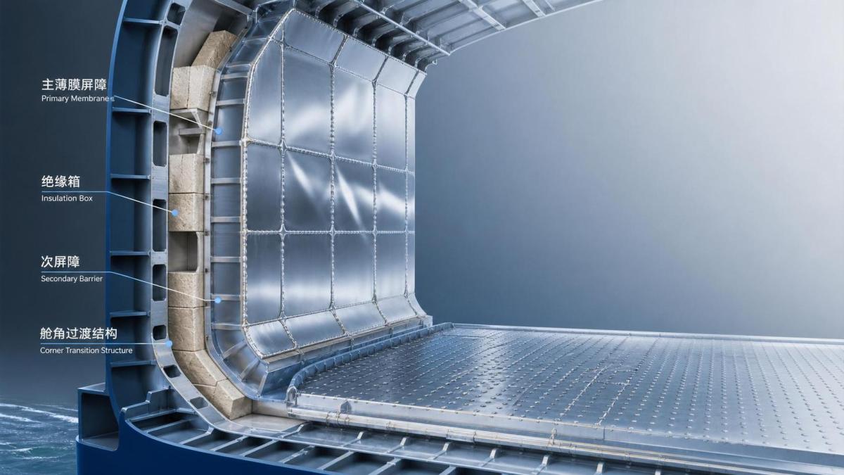
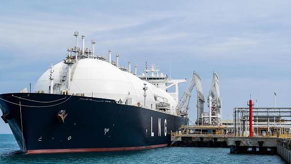
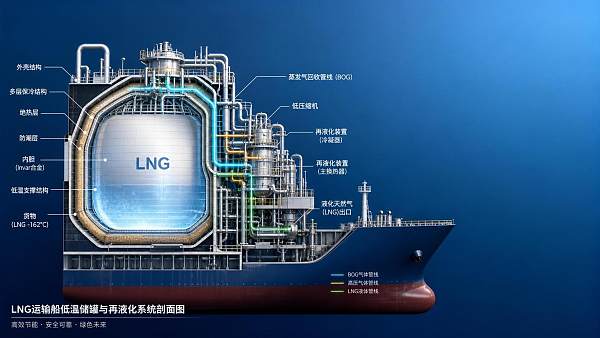
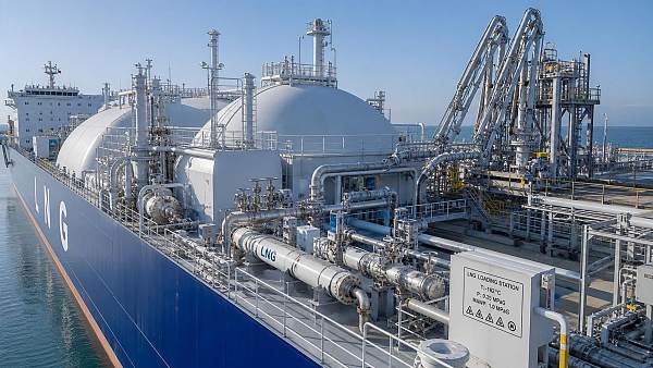
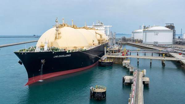
Membrane containment systems sit at the center of LNG carrier safety. They hold cargo at about minus 163 degrees Celsius while limiting boil-off and protecting the hull.
That sounds straightforward, yet the engineering margin is tight. A small defect can grow through repeated thermal cycling, sloshing loads, or poor installation discipline.
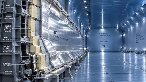
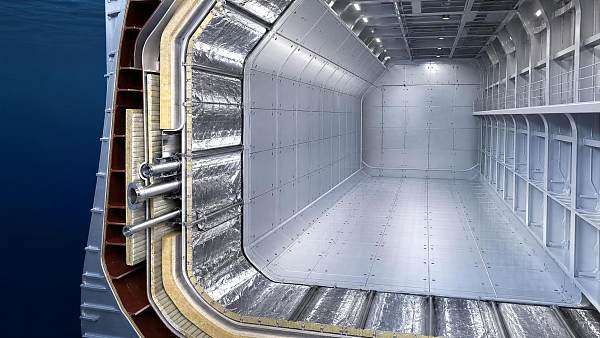
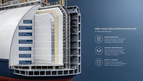
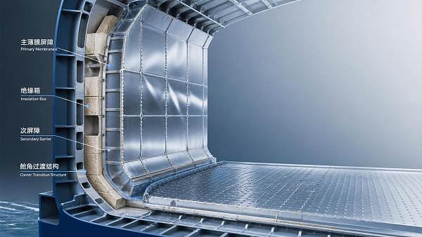
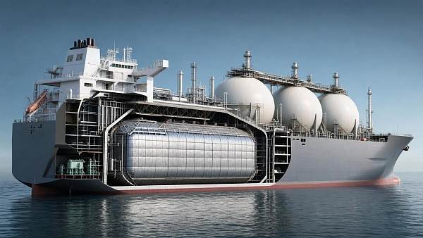
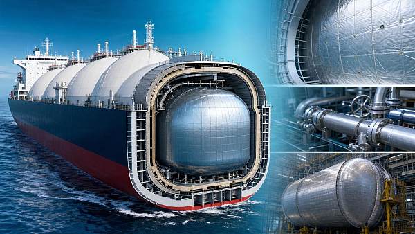
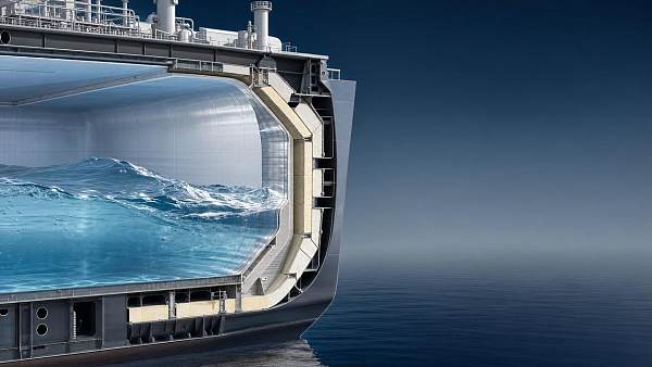
In practice, membrane containment systems are not judged by one component alone. Primary barrier behavior, insulation boxes, secondary barrier continuity, and inner hull interface all matter together.
This is one reason GTOT tracks cryogenic vessel intelligence alongside rail control and traction systems. Across land and sea equipment, reliability comes from controlling invisible failure chains before they become operational events.
The real question is not whether membrane containment systems are advanced. It is where they are most likely to fail, and what evidence should trigger earlier intervention.
Where do membrane containment systems usually start to fail?
Early damage rarely begins as a dramatic rupture. More often, membrane containment systems show weak signals long before loss of containment becomes visible.
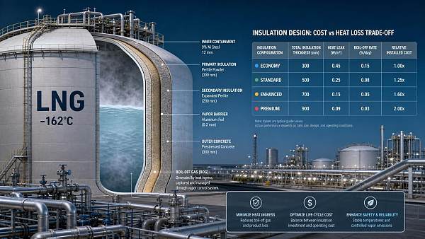
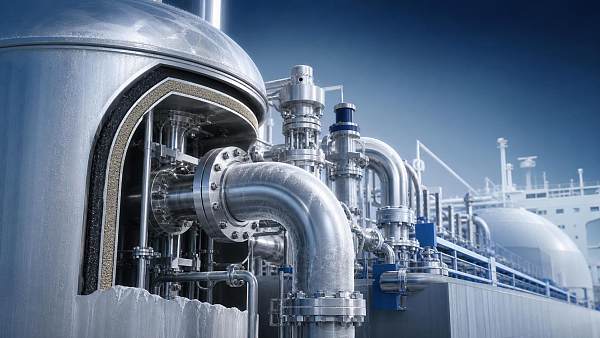
The first pattern is insulation degradation. If insulation compresses, absorbs moisture, or loses dimensional stability, local heat ingress rises and stress distribution changes.
Another common source is stress concentration around corners, pump tower interfaces, corrugation transitions, and weld details. Cryogenic contraction amplifies design and fabrication inaccuracies.
Secondary barrier damage is also underestimated. Operators sometimes focus on the visible primary barrier, while hidden damage behind it quietly reduces redundancy.
Sloshing impact adds another layer. Partial filling conditions can generate repeated pressure pulses, especially on large tanks during rough weather or non-ideal voyage planning.
A practical way to view the risk is this: membrane containment systems fail when thermal, mechanical, and workmanship deviations accumulate faster than inspection can detect them.
Quick risk map for recurring failure signals
The table below helps organize the most common warning areas and the checks that usually provide the clearest technical value.
Is insulation degradation really as serious as weld failure?
Yes, and often more deceptive. Weld failure gets attention because it feels critical. Insulation degradation is dangerous because it changes system behavior before anyone sees a crack.
When membrane containment systems lose insulation performance, heat ingress increases. That affects boil-off, but it also shifts temperature gradients across materials with different expansion behavior.
Over time, those gradients can raise local stress, reduce support uniformity, and disturb the design assumptions behind membrane flexibility. The result may appear elsewhere, not at the insulation defect itself.
A frequent mistake is treating insulation only as an efficiency topic. In LNG tank design, insulation condition is also a structural reliability topic.
Useful checks usually include:
- verifying moisture exposure during storage and installation;
- reviewing compression and flatness tolerances at support interfaces;
- tracking unexplained boil-off deviations over comparable voyages;
- comparing repair history against recurring cold spot indications.
If membrane containment systems show both thermal anomalies and recurring local repairs, that combination deserves escalation rather than routine closure.
How do stress concentration and sloshing turn into actual damage?
Stress concentration is not just a calculation issue. It becomes physical damage when repeated loads exceed what local geometry and workmanship can absorb over time.
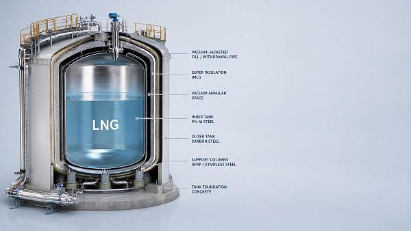
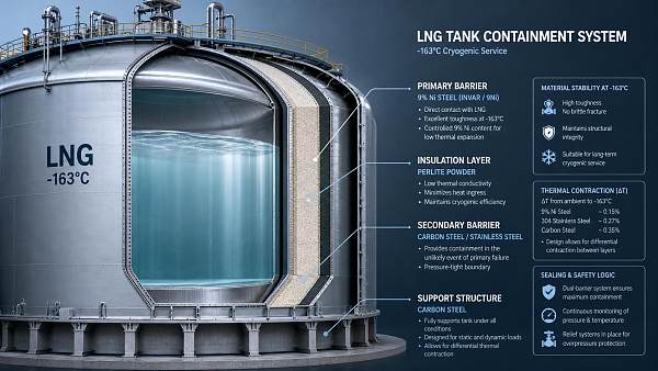
Membrane containment systems rely on thin metallic barriers supported by insulation structures. That architecture performs well, but it is sensitive to local discontinuities.
Common high-risk locations include corners, chamfered transitions, dome areas, equipment supports, and welded intersections. Even minor out-of-tolerance conditions can intensify cyclic strain.
Sloshing makes the picture harsher. In partially filled tanks, LNG impacts can create short-duration but high-energy loads. Those loads are difficult because they are irregular and route dependent.
More careful teams do not wait for visible membrane distress. They compare filling patterns, weather exposure, and tank management records with hot spots found during survey cycles.
This is where technical intelligence matters. GTOT often frames membrane containment systems the same way other safety-critical transport systems are judged: by load paths, failure propagation, and verification discipline.
What evidence usually matters most?
- Repeated repairs at similar coordinates or structural zones.
- Unexpected strain concentration from monitoring or model updates.
- Changes in allowed filling limits after service experience.
- Misalignment between design assumptions and real voyage profiles.
What inspection blind spots cause secondary barrier problems to be missed?
The secondary barrier is easy to under-prioritize because it is not the first line of cargo containment. That thinking is risky.
In membrane containment systems, the secondary barrier exists to contain leakage long enough for detection and controlled response. If it is compromised, resilience drops sharply.
One blind spot is fragmented documentation. Repair records, material traceability, and hold-point approvals may sit in separate systems and never get reviewed as one chain.
Another blind spot is assuming that a passed leak test closes the issue. A local pass does not always confirm long-term durability after thermal cycling and ship motion.
Membrane containment systems benefit from inspections that connect workmanship evidence with service exposure. A repair that was acceptable at delivery may deserve renewed scrutiny after heavy sloshing history.
The more reliable approach is to ask whether secondary barrier integrity remains demonstrable, not merely whether it once passed a certification step.
How should failure risk be judged before it becomes a costly incident?
The best judgment method combines design review, build quality evidence, and service data. Membrane containment systems are too complex for checklist thinking alone.
A useful screening approach is to separate red flags into three groups: geometry-related, material-related, and operation-related. Problems usually escalate where those groups overlap.
For example, a marginal weld area becomes more serious if insulation support is uneven and the tank has frequent partial-fill operation in rough seas.
Before accepting risk as manageable, it helps to confirm the following points:
- Whether design stress assumptions match actual loading patterns.
- Whether installation tolerances stayed within verified limits.
- Whether recurring anomalies have a closed root-cause loop.
- Whether secondary barrier status is proven after repairs.
- Whether thermal performance trends remain stable over time.
If two or more answers remain uncertain, membrane containment systems usually need deeper engineering review rather than routine operational acceptance.
What is the practical next step when membrane containment systems show warning signs?
Start by organizing evidence, not opinions. Gather inspection history, voyage conditions, filling profiles, repair locations, boil-off trends, and any updated stress calculations.
Then rank the warning signs by propagation potential. A small hidden defect in a critical transition zone may matter more than a visible but stable superficial issue.
For membrane containment systems, good decisions usually come from linking three views: what the design intended, what construction delivered, and what service conditions actually imposed.
That cross-check is increasingly important in global transport, where fleet utilization pressure can quietly narrow maintenance margins. It is also why technical platforms such as GTOT emphasize evidence-led intelligence over isolated news updates.
The most useful next move is to build a focused review standard for membrane containment systems. Include insulation condition, stress hot spots, secondary barrier traceability, and sloshing-sensitive operating windows.
When those elements are reviewed together, failure risk becomes easier to judge early, and costly surprises become far less likely.
Recommended News
 Sep 28, 2026When is nickel steel containment needed for cryogenic storage?Nickel steel containment is essential when cryogenic tanks face brittle-fracture risk. Discover how temperature, loads, and tank design guide the right choice.
 Sep 11, 2026How membrane containment systems demonstrate compliance with IMO standardsMembrane containment systems IMO standards: discover how LNG carriers prove compliance through verified barriers, testing, monitoring, and traceable records.
 Sep 10, 2026How membrane and Moss containment systems differ for LNG carriersLNG cargo containment for carriers: compare membrane and Moss systems for capacity, BOG, safety, sloshing, lifecycle cost, and operational flexibility.
 Sep 03, 2026What drives membrane containment systems cost in LNG projects?Membrane containment systems cost depends on tank design, materials, labor, QA, and boil-off performance. Discover how to control LNG project risk and lifecycle costs.
 Aug 11, 2026How Vacuum Insulated Cryogenic Engineering Reduces Boil-Off and Heat LeakVacuum insulated cryogenic engineering cuts boil-off and heat leak by optimizing vacuum spaces, MLI, supports, and penetrations—discover what really improves LNG thermal performance.
 Aug 09, 2026What Determines Safe Cryogenic Containment Design in LNG Storage?Cryogenic containment design in LNG storage depends on materials, thermal stress, leak control, and BOG management. Discover what truly defines safe, code-compliant performance.
 Jul 29, 2026How to Evaluate a Cryogenic Tank Handling System for LNG Transfer SafetyCryogenic tank handling system evaluation for LNG transfer safety: learn how to assess pressure control, insulation, ESD response, and operational reliability before choosing a safer system.
 Jul 24, 2026Deep-Cryogenic Insulation Systems Cost: What Drives Total Project Spend?Deep-cryogenic insulation systems cost depends on design, materials, installation, QA, and boil-off performance. Learn what drives total project spend and compare bids with confidence.
 Jul 21, 2026LNG Carriers Class Approval: Key Rules and Compliance RisksLNG carriers class approval explained: key rules, major compliance risks, and practical steps to prevent delays, protect vessel readiness, and improve charter confidence.
 Jul 15, 2026Low Boil Off Insulation System Performance: What Reduces LNG Losses MostLow boil off insulation system performance explained: discover what cuts LNG losses most through smarter containment, installation quality, and BOG management.
 Jul 13, 2026Deep Cryogenic Insulation for LNG Tanks: Cost vs Heat LossDeep cryogenic insulation for LNG tanks impacts more than upfront cost. Learn how lower heat loss cuts BOG, improves efficiency, and strengthens lifecycle value.
 Jul 13, 2026Low Loss Cryogenic Handling: Key Factors for Safer TransferLow loss cryogenic handling starts with thermal control, pressure balance, and clean transfer. Learn the key factors that reduce boil-off, protect product integrity, and improve safer LNG and industrial operations.
 Jul 12, 2026LNG Vessel Fuel Storage: Main Safety Risks and FixesLNG vessel fuel storage safety starts with early risk detection. Learn the main hazards, warning signs, and practical fixes to reduce leaks, pressure instability, and onboard failures.
 Jul 09, 2026Membrane Cargo Tank vs Moss Type: Which Fits Modern LNG FleetsMembrane cargo tank vs Moss type: compare LNG fleet capacity, boil-off strategy, maintenance, and asset value to choose the best-fit design for modern shipping returns.
 Jul 08, 2026Membrane Containment Systems: Key Failure Risks in LNG Tank DesignMembrane containment systems are central to LNG tank safety. Explore key failure risks, from insulation degradation to sloshing and secondary barrier issues, and learn what to check early.
 Jul 06, 2026How to Compare a Cryogenic Shipping Systems Manufacturer for Long-Haul LNG ProjectsCryogenic shipping systems manufacturer selection can make or break long-haul LNG projects. Compare boil-off control, compliance, engineering support, and lifecycle value.
 Jul 02, 2026Cryogenic Shipping Safety: Common Failure Risks and FixesCryogenic shipping safety starts with finding hidden failure risks early. Learn the main causes, practical fixes, and audit gaps that help protect LNG cargo, cut incidents, and improve control.
 Jul 02, 2026LNG Carriers Dimensions Explained for Terminal PlanningLNG carriers dimensions explained for smarter terminal planning. Learn how vessel size affects berth design, draft limits, mooring, and future fleet compatibility.
 Jun 30, 2026LNG Carrier Containment Technology Explained: Membrane vs Moss SystemsLNG carrier containment technology explained clearly: compare membrane vs Moss systems, key trade-offs, cargo efficiency, sloshing risk, and what drives smarter LNG vessel decisions.
 Jun 30, 2026Vacuum Deep Cryogenic Insulation: Key Failure Risks and How to Prevent ThemVacuum deep cryogenic insulation failure can raise boil-off, safety, and compliance risks. Learn key warning signs, root causes, and practical prevention steps to protect LNG operations.
 Jun 28, 2026Deep-Cryogenic Insulation Cost: What Drives Budget Changes in LNG ProjectsDeep-cryogenic insulation cost in LNG projects depends on materials, containment design, labor, compliance, and shipyard execution. Learn what drives budget changes and how to control risk.
 Jun 25, 2026Cryogenic Shipping Solutions: Key Risks, Costs, and Containment ChoicesCryogenic shipping solutions: compare key risks, lifecycle costs, and membrane vs. Moss containment to avoid hidden losses and choose safer, more efficient LNG transport.
 Jun 15, 2026Cryogenic Engineering Basics: Key Design Factors for Containment SafetyCryogenic engineering basics explained: discover the key design factors behind safer LNG and low-temperature containment, from materials and thermal stress to boil-off control and monitoring.
 Jun 11, 2026Membrane Containment Systems: Key Failure Risks and Design ChecksMembrane containment systems demand rigorous design checks. Explore key failure risks, from sloshing stress to insulation aging, and learn how to improve LNG vessel safety and compliance.