



Search News
Industry Portal
Popular Tags
How to select railway signaling relays for fail-safe circuits
Author
Time
Click Count
Selecting railway signaling relays for fail-safe circuits is not a matter of finding a device with the right coil voltage and enough contacts. In a signaling room, an interlocking cabinet, or a trackside equipment enclosure, a relay may sit quietly for years—until one unexpected condition makes its behavior decisive. A broken wire, declining supply voltage, water ingress, welded contact, maintenance error, or transient surge must not create a permissive indication when the railway should be protected.
For technical evaluators, the central question is therefore not simply, “Will this relay switch?” It is: “When this relay, its wiring, or its supply is degraded, does the circuit move to, or remain in, the safest defined state?” That question shapes every part of the selection process: relay architecture, contact arrangement, insulation, environmental qualification, diagnostic strategy, documentation, and system safety evidence.
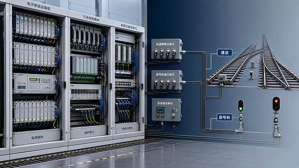
In fail-safe railway applications, relays are rarely assessed as isolated catalogue items. They are evaluated as controlled elements within a wider safety function—such as route locking, point detection, signal proving, track occupancy logic, level-crossing control, or emergency traction isolation. The strongest procurement decisions reflect that system context from the beginning.
Start with the safety function, not the relay datasheet
A common mistake is to begin with a list of electrical ratings: 24 VDC coil, four changeover contacts, plug-in mounting, specified switching current. Those values matter, but they do not establish whether a relay is suitable for a safety-critical circuit.
Before comparing railway signaling relays, define the intended safe state in plain operational language. For example:
- Loss of energization must cause a signal aspect to become restrictive.
- A broken control wire must prevent route release.
- Loss of proving must hold points locked or inhibit movement authority.
- An uncertain field indication must be treated as “not proved,” rather than accepted as healthy.
This is the familiar de-energize-to-trip principle, but it needs careful interpretation. A relay circuit is only fail-safe when the full chain supports it: supply arrangement, cable supervision, contact logic, input conditioning, output loads, and any software or electronic interface. A relay that drops out safely is of little value if a parallel path can still energize a permissive output.
Document the functional logic before selecting hardware. A concise cause-and-effect matrix should show what happens during normal operation, coil loss, short circuit, open circuit, contact failure, supply undervoltage, and restoration of power. This gives evaluators a practical basis for identifying which relay characteristics are safety-relevant and which are merely installation preferences.
What makes a signaling relay different from a general-purpose relay?
Industrial relays may perform well in automation cabinets, yet their construction, failure behavior, traceability, and testing regime may not satisfy railway signaling expectations. Signaling duty has traditionally favored relay designs that make abnormal states observable, limit the risk of false pickup, and support rigorous inspection throughout a long service life.
The exact requirements vary by railway authority, country, interlocking generation, and whether the application is wayside, onboard, depot-based, or part of a migration interface. Still, an evaluator should look for evidence that the relay is intended for the relevant railway environment rather than merely sold into it.
Read the coil data as a safety parameter
Coil nominal voltage alone tells very little. The critical values are pickup voltage, dropout voltage, release time, coil resistance or power consumption, and tolerance across the full operating temperature range. In a fail-safe design, the release threshold must be understood in relation to the lowest credible supply voltage, cable voltage drop, battery discharge condition, and transient disturbances.
Suppose a relay is intended to remain energized only when a control circuit is healthy. If its dropout voltage is too low, it may stay picked up during a degraded supply condition that the system intended to detect. If it drops out too readily, nuisance releases may reduce availability and encourage unsafe maintenance workarounds. Neither extreme is acceptable without a system-level justification.
Also examine suppression arrangements. DC coil flyback diodes, resistors, varistors, and RC networks influence release time and electromagnetic emissions. A simple diode can significantly extend de-energization time. That may be harmless in one non-safety auxiliary circuit but unacceptable where timing is part of route release or signal control logic. The relay, suppression device, and driving output must be evaluated together.
Contact arrangements: count functionally, not just numerically
A relay advertised as having “six contacts” may still be unsuitable if the required safety logic depends on segregation, independent contact paths, or mechanically related status. Technical teams should map each contact to its role rather than treating all poles as interchangeable.
Normally closed contacts are often central to de-energize-to-trip logic, but a normally closed symbol on a schematic is not proof of fail-safe performance. Consider the plausible dangerous modes: welded normally open contacts, failed-open normally closed contacts, contact bridging, incorrect terminal connection, or a relay armature that does not fully release.
Where the safety function relies on correlated contact states, positively driven or mechanically linked contact arrangements may provide a more defensible design basis. Their value lies in making certain combinations physically constrained, helping diagnostics reveal a discrepancy. However, no contact mechanism eliminates the need for circuit supervision. A signaling design should detect contradictions where feasible, such as an output reported active while its proving return is absent.
Contact material and load type deserve equal attention. Low-level monitoring currents can suffer from oxidation or film formation, while inductive loads generate arcing and contact erosion. A relay that is adequate for a resistive lamp indication may behave very differently when switching a solenoid, a contactor coil, or an electronic input with inrush current. Request switching-life information for the actual load category, duty cycle, and suppression method—not only a headline electrical life figure.

Assess insulation, separation, and external fault exposure
Railway signaling installations often combine battery supplies, field cables, lightning-prone outdoor circuits, logic interfaces, and communications equipment in confined spaces. A relay can become an unintended fault bridge if insulation coordination is weak or terminal separation is poorly matched to the wiring design.
Review creepage distance, clearance, dielectric strength, and impulse withstand against the relevant system voltage and overvoltage environment. The required margin is not determined by the coil voltage alone. Cable length, location, surge protection architecture, earthing arrangement, pollution degree, humidity, and nearby traction power infrastructure all influence exposure.
Pay particular attention to separation between safety-related and non-safety-related circuits. If a non-safety auxiliary source can backfeed a vital circuit through shared contacts, common terminals, test links, or terminal blocks, the apparent redundancy may be illusory. The relay selection process should therefore include terminal layout drawings and wiring interface reviews, not only electrical schematics.
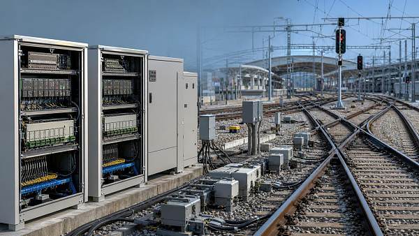
For trackside applications, environmental sealing must be considered realistically. An enclosure rating does not remove the need to evaluate condensation, conductive dust, salt-laden air in coastal corridors, pest ingress, and repeated temperature cycling. In marine-adjacent rail networks and freight terminals, atmospheric corrosion can be as relevant as vibration.
Environment is not a procurement footnote
Railway relay performance can drift under heat, cold, vibration, shock, and contamination. A cabinet-mounted relay in a climate-controlled signaling equipment room faces a very different duty profile from one installed in an outdoor relay room, a lineside case, or an onboard traction-adjacent cabinet.
Ask suppliers to identify the applicable environmental evidence and test methods rather than relying on broad statements such as “railway grade.” Depending on the application and governing project specification, the review may involve electromagnetic compatibility requirements, vibration and shock performance, temperature and humidity cycling, fire and smoke constraints, and insulation coordination. Relevant CENELEC or IEC standards may inform this assessment, but the project safety case and local railway authority requirements remain the deciding framework.
It is equally important to assess electromagnetic behavior as part of the installed circuit. Fast switching outputs, nearby radio systems, traction return currents, and surge events can all affect relay coil energization or contact monitoring. Shielding, grounding, cable routing, and surge protection may be more influential than a single relay specification line.
Documentation is part of the safety evidence
For a non-critical panel, a datasheet may be enough. For fail-safe railway circuits, evaluators should expect a deeper evidence package. The goal is not to create paperwork for its own sake; it is to show that the chosen device can be justified, reproduced, maintained, and replaced without silently changing the safety argument.
A useful supplier review normally includes:
- Detailed drawings showing pinout, contact form, terminal identification, dimensions, and mechanical keying.
- Coil pickup and dropout characteristics, including tolerances and test conditions.
- Contact ratings by load type, electrical endurance data, and recommended suppression practices.
- Environmental, EMC, insulation, vibration, and shock test evidence relevant to the installation.
- Manufacturing traceability, configuration control, change-notification process, and counterfeit prevention measures.
- Maintenance instructions, inspection intervals where applicable, storage limitations, and end-of-life policy.
For higher-integrity projects, connect this material to the wider assurance process under applicable railway safety standards, such as the EN 50126, EN 50128, EN 50129, or IEC 62425 family where relevant. A relay is not automatically “SIL4” because it is used in a SIL4 system. The claim belongs to the safety function and must be supported by the complete design, hazard analysis, verification strategy, and operational controls.
Where selection decisions often go wrong
Choosing by nominal equivalence. A replacement relay with matching voltage, dimensions, and contact count may have different dropout values, timing, contact material, or internal construction. Treat substitutions as engineering changes, not warehouse decisions.
Ignoring the de-energization path. Teams sometimes analyze how the relay picks up but do not model how quickly and reliably it releases. Coil suppression, shared returns, stored energy, and backfeed paths can all delay or defeat the intended safe state.
Assuming redundancy solves every failure. Two relays in parallel can increase availability while also creating common-cause vulnerabilities through common power, common terminals, shared environmental exposure, or identical systematic defects. Independence has to be demonstrated, not assumed.
Overlooking testability. A circuit may be logically safe yet difficult to inspect. If technicians cannot verify relay release, contact continuity, wiring integrity, and correct replacement orientation without bypassing protection, field reliability will suffer over time.
A practical selection sequence for technical evaluators
Begin with a hazard-driven circuit review and define the safe state for every loss-of-energy and fault condition. Then translate the logic into measurable relay requirements: threshold behavior, contact relationships, isolation levels, timing limits, load duty, and environmental envelope.
Next, compare candidate railway signaling relays using a weighted compliance matrix. Separate “mandatory safety requirements” from “preferred commercial features.” A lower-cost relay should not remain in consideration if it cannot provide evidence for a safety-critical requirement. Conversely, a highly specified device should not be selected merely because it has an impressive qualification portfolio if its coil and contact behavior do not suit the actual logic.
Prototype testing should reproduce credible boundary conditions: minimum and maximum supply, temperature extremes, representative cable resistance, switched load inrush, surge protection configuration, and anticipated vibration. Verify not only that the relay works, but that the complete circuit fails in the intended direction.
Finally, establish a controlled approval baseline. Record the approved relay part number, revision, socket or base arrangement, suppression components, wiring diagram, test procedure, and substitution rules. This discipline protects the installation long after the original design review is forgotten.
At GTOT, our railway control intelligence focuses on the practical connection between component-level decisions and interlocking integrity. The most dependable relay selection is rarely the one with the longest feature list. It is the one whose behavior under fault, environment, maintenance, and lifecycle change is clearly understood—and whose place in the fail-safe circuit can be defended with evidence.
Recommended News
 Sep 30, 2026How to select railway signaling relays for fail-safe circuitsRailway signaling relays: learn how to select fail-safe designs with proven coil behavior, contact logic, insulation, and railway-grade reliability.
 Aug 29, 2026What to verify before choosing a railway interlocking equipment exporterRailway interlocking equipment exporter checklist: verify safety evidence, interfaces, engineering, traceability, export readiness, and long-term support before procurement.
 Aug 15, 2026How to choose railway interlocking equipment for junctionsRailway interlocking equipment for junctions: learn how to choose the right system for safety, capacity, and future expansion with confidence.
 Jul 14, 2026Rail Interlocking Systems: Common Failure Risks and Design ChecksRail interlocking systems face critical risks from route locking, point detection, track vacancy, and interface timing. Learn the key design checks that improve safety and reduce commissioning risk.
 Jul 06, 2026When to Choose a SIL4 Signalling Equipment Integrator Over Multiple VendorsSIL4 signalling equipment integrator or multiple vendors? Learn when unified integration reduces interface risk, speeds safety approval, and protects rail project delivery.
 Jul 01, 2026Electronic Railway Interlocking Systems: Key Failure Risks and Compliance ChecksRailway interlocking systems electronic risks can disrupt safety, uptime, and compliance. Explore key failure points, practical checks, and proven ways to strengthen rail resilience.
 Jun 23, 2026Interlocking Systems: Key Failure Risks and Safety Checks Before DeploymentInterlocking systems: discover key failure risks, interface hazards, and must-do safety checks before deployment to prevent costly incidents and ensure fail-safe performance.
 Jun 19, 2026Interlocking Systems for Railway Safety: Key Standards and Failure RisksInterlocking systems for railway safety: explore key standards, SIL4 expectations, and hidden failure risks to strengthen railway compliance, resilience, and safe operations.
 Jun 10, 2026How Interlocking Systems Reduce Rail Network Failure RiskInterlocking systems reduce rail network failure risk by preventing conflicts, containing faults, and speeding recovery. See how they improve safety, uptime, and operational resilience.
 Jun 05, 2026Railway Control Components: Key Failure Points to AvoidRailway control components fail in different ways across urban, high-speed, freight, and harsh outdoor routes. Discover the key failure points to avoid for safer, more reliable rail operations.
 Jun 03, 2026Railway Signal Control Systems: Common Failure Points and Safety ChecksRailway signal control systems require rigorous safety checks. Discover common failure points, inspection priorities, and practical steps to reduce risk and protect rail operations.
 Jun 02, 2026How to Evaluate Railway Control Components for System ReliabilityRailway control components evaluation guide: assess SIL compliance, interoperability, stress testing, cybersecurity, and lifecycle reliability for safer rail systems.
 May 31, 2026Interlocking Systems Technology Standards: Key Compliance RisksInterlocking systems technology standards expose critical compliance risks in SIL validation, cybersecurity, and traceability—learn how to protect rail safety and approvals.
 May 28, 2026Interlocking Systems for High-Density Rail Operations: What Improves Capacity Safely?Interlocking systems for high-density rail operations: discover how SIL4-safe architectures, redundancy, and automation interfaces boost rail capacity, resilience, and future readiness.
 May 26, 2026Interlocking Systems for Railway Safety: How to Compare Failure RisksInterlocking systems for railway safety: compare failure risks through design logic, diagnostics, redundancy, and lifecycle factors to make safer, smarter rail decisions.
 May 21, 2026Interlocking Systems Technology Standards: Key Compliance Checks for 2026Interlocking systems technology standards guide 2026 rail compliance checks on safety traceability, software control, cybersecurity, and field integrity. Learn key risks and practical actions.
 May 20, 2026Interlocking Systems for High-Density Rail: Capacity Gains vs Safety TradeoffsInterlocking systems for high-density rail operations: explore how modern architectures boost rail capacity, reduce headways, and manage safety tradeoffs for smarter network planning.
 May 19, 2026Interlocking Systems for Railway Safety: Choosing for Retrofit ProjectsInterlocking systems for railway safety: learn how to choose the best retrofit path with SIL4 assurance, legacy compatibility, lower risk, and future-ready performance.
 May 17, 2026How Computer Interlocking Cuts Rail Signaling Failure RiskInterlocking systems cut rail signaling failure risk by preventing route conflicts, reducing human error, and supporting SIL4 safety—see how computer interlocking boosts reliable, high-density operations.