



Search News
Industry Portal
Popular Tags
What to assess before selecting an electric traction system manufacturer
Author
Time
Click Count
Selecting an electric traction system manufacturer is a lifecycle engineering decision, not a catalogue comparison. The preferred supplier must prove performance under your actual operating conditions.
Technical evaluators should start by defining duty cycles, route characteristics, energy objectives, interface constraints, safety obligations, and maintenance capabilities before comparing proposed traction equipment.
The strongest manufacturer is rarely the one offering the highest peak power or lowest purchase price. It is the partner that can demonstrate dependable integration, predictable availability, and controlled lifecycle risk.
This guide helps railway technical teams assess electric traction system manufacturers for high-speed, urban, regional, freight, and heavy-duty rail applications using evidence-based selection criteria.
Start with the Actual Operating Envelope
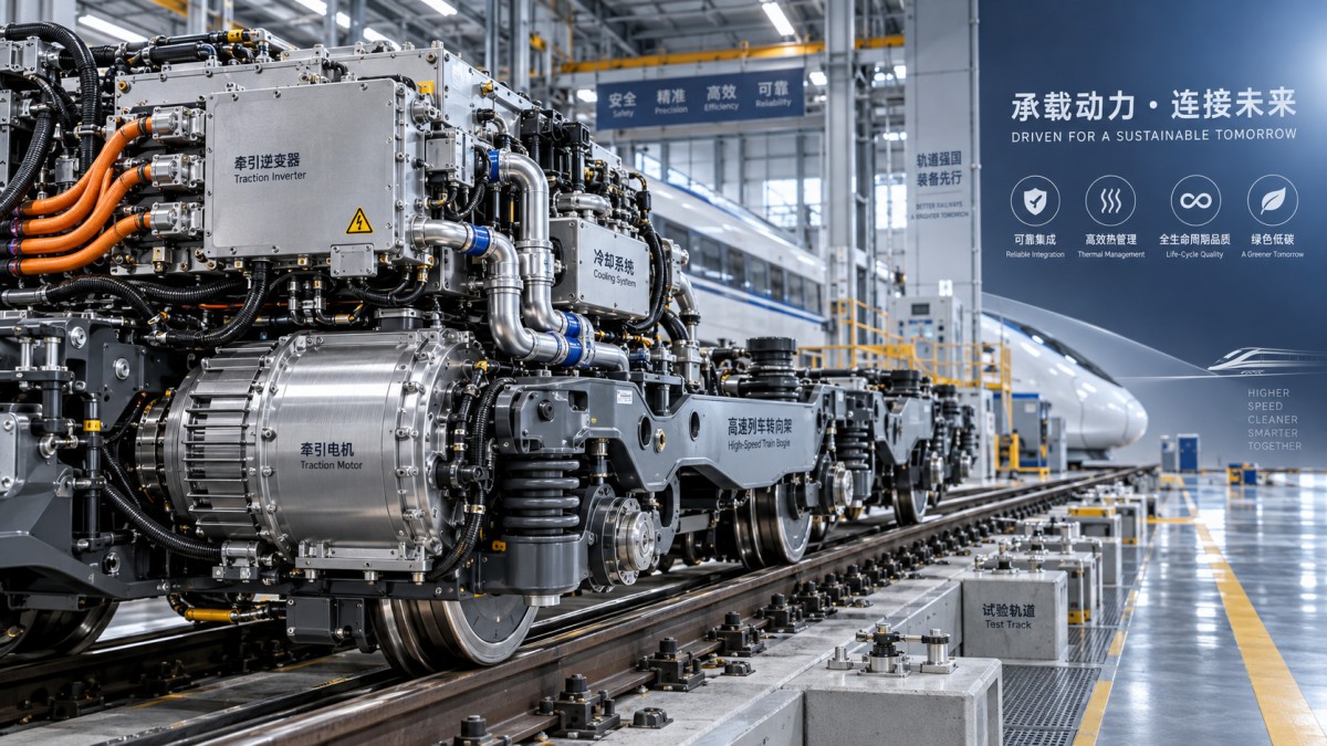
Before reviewing supplier proposals, translate the vehicle mission into measurable traction requirements. A generic power rating cannot show whether a system will survive the operational environment.
Document maximum gradients, station spacing, route speed, axle loads, passenger density, train length, braking frequency, ambient temperature, altitude, and expected service availability targets.
Urban metro vehicles typically demand frequent acceleration, regenerative braking, short dwell times, and high daily mileage. Freight locomotives require sustained tractive effort and thermal endurance.
High-speed applications introduce further concerns, including aerodynamic loads, power collection variability, strict electromagnetic compatibility, and stable torque delivery across extended high-speed operation.
Ask each electric traction system manufacturer to model performance against your stated mission profile rather than presenting nominal values from an unrelated reference project.
The model should identify acceleration margins, continuous power limits, adhesion assumptions, regenerative braking recovery, inverter temperatures, motor temperatures, and predicted energy consumption.
Suppliers should clearly distinguish between short-duration peak ratings and continuously sustainable ratings. Confusing these values can produce overheating, reduced availability, and later operational restrictions.
Evaluate degraded-mode performance as carefully as normal operation. Determine whether a train can complete a journey, clear critical sections, or reach maintenance facilities after component failures.
Consider future operating changes during this stage. Increased passenger loading, timetable compression, network extensions, or higher ambient temperatures can consume design margins surprisingly quickly.
A manufacturer that challenges incomplete assumptions and requests route data is often more credible than one that immediately confirms every requirement without qualification.
Assess Traction Architecture and System Integration
An electric traction system is an integrated chain comprising transformers or converters, traction inverters, motors, gearboxes, auxiliary interfaces, brake controls, diagnostics, and vehicle control networks.
Review whether the proposed architecture matches the vehicle platform, supply voltage, axle arrangement, available installation space, cooling concept, and redundancy philosophy.
For AC electrified railways, assess transformer design, input conversion, harmonic management, insulation coordination, and behavior during voltage fluctuations or short supply interruptions.
For battery-electric or hybrid vehicles, examine battery interface specifications, charging behavior, energy-management logic, isolation monitoring, and protection coordination under fault conditions.
Integration quality often determines project success more than individual component efficiency. Interfaces between traction controls, braking systems, pantographs, and train control systems require disciplined engineering ownership.
Ask who owns system-level verification when an issue crosses supplier boundaries. A reliable manufacturer provides named technical responsibility rather than attributing every integration problem to another contractor.
Network compatibility deserves specific scrutiny. Confirm supported protocols, message timing, cybersecurity controls, diagnostic access, software version management, and requirements for proprietary tools or licenses.
Evaluate how the traction controller coordinates electric, pneumatic, and blended braking. Poor blending logic can affect stopping consistency, brake wear, wheel-slide protection, and energy recovery.
Request interface control documents early. These should define electrical, mechanical, thermal, communication, safety, commissioning, and maintenance responsibilities with sufficient testable detail.
Manufacturers with demonstrated experience integrating into comparable vehicle architectures generally reduce commissioning uncertainty, especially where several international suppliers contribute critical subsystems.
Verify Thermal Performance Beyond Nameplate Power
Thermal design is one of the most important differentiators among traction suppliers because heat directly influences reliability, efficiency, component ageing, and permissible operating duty.
Review cooling methods for converters, motors, transformers, and power electronics. Air cooling, liquid cooling, and hybrid systems create different maintenance demands and failure modes.
Demand thermal calculations based on maximum expected ambient conditions, blocked airflow scenarios, fouled filters, extended gradients, repeated acceleration, and reduced cooling-system performance.
Ambient temperatures on vehicles can significantly exceed external weather readings. Roof equipment, underfloor enclosures, tunnels, depots, and constrained ventilation create localized thermal stress.
Ask for temperature derating curves that show exactly when the traction system reduces output. A stated maximum power figure has limited value without these operational boundaries.
Cooling hardware should be assessed for accessibility. Fans, pumps, heat exchangers, sensors, hoses, filters, and coolant connections need practical inspection and replacement procedures.
Examine whether the manufacturer has validated thermal behavior using representative duty cycles, not only laboratory steady-state tests. Transient heating can expose weaknesses hidden by simplified testing.
Traction motor insulation class, bearing protection, winding temperature measurement, and vibration resistance should be reviewed together because temperature and mechanical stress often interact.
For coastal, desert, or polluted environments, ask about corrosion protection, particulate ingress, humidity tolerance, salt mist testing, and long-term degradation of cooling surfaces.
A technically mature proposal explains thermal margins transparently, including limits and assumptions. Vague assurances about robust cooling should not substitute for validated engineering evidence.
Examine Reliability, Maintainability, and Lifecycle Evidence
Reliability claims should be supported by fleet evidence, failure data, and maintenance records. Technical evaluators need to distinguish proven field performance from predicted laboratory reliability.
Request mean time between failure data by subsystem, including converters, motors, cooling units, control electronics, sensors, contactors, and auxiliary power interfaces.
Ask how the manufacturer defines a failure event. Comparable statistics require consistent treatment of service interruptions, minor defects, software resets, depot interventions, and component replacements.
Reference fleets should resemble your application in climate, utilization, power supply, axle load, route profile, and maintenance regime. A lightly used fleet is not equivalent evidence.
Examine corrective maintenance history alongside scheduled maintenance requirements. Components that appear reliable may still impose costly inspection, calibration, cleaning, or replacement intervals.
Assess the accessibility of high-failure items. Maintenance technicians should not need extensive dismantling, special lifting equipment, or long isolation procedures for routine replacement tasks.
Modular designs can reduce downtime, but only when modules are genuinely interchangeable, available locally, and configurable without lengthy software commissioning or complex calibration.
Review spare-parts forecasts for the full intended operating period. Include obsolescence management, lead times, repair turnaround, minimum stock recommendations, and local warehousing arrangements.
Software support is part of maintainability. Confirm how diagnostic tools are licensed, who can access fault data, and how updates are validated before fleet-wide deployment.
A capable electric traction system manufacturer provides root-cause analysis processes, corrective-action tracking, and transparent escalation paths when repeated field faults affect availability targets.
Confirm Safety, Compliance, and Cybersecurity Readiness
Compliance must be assessed as a system obligation, not a documentation exercise. The traction package must support the vehicle's safety case and applicable national railway approvals.
Confirm applicable standards early, including requirements for fire safety, electromagnetic compatibility, electrical insulation, environmental testing, functional safety, and railway-specific certification.
For European projects, relevant requirements may include EN 50155, EN 45545, EN 50121, EN 61373, EN 50126, EN 50128, and EN 50129.
Standards alone do not prove safe behavior. Ask to review hazard analyses covering overcurrent, loss of cooling, unintended torque, isolation faults, overspeed, communication loss, and emergency braking.
Safety-related traction functions should have traceable requirements, verification records, software configuration control, and clear evidence of independent assessment where required by the project.
Electromagnetic compatibility deserves careful review because traction switching can interfere with signalling, communications, passenger systems, axle counters, and onboard train control equipment.
Ask for conducted and radiated emissions results, immunity test reports, installation constraints, bonding requirements, cable-routing guidance, and evidence from comparable railway environments.
Connected traction systems also introduce cybersecurity considerations. Assess authentication, network segmentation, secure update processes, audit logs, vulnerability management, and remote-access controls.
Clarify data ownership and access rights. Operators need usable fault and performance data throughout the contract, without becoming dependent on a supplier-controlled monitoring platform.
Manufacturers that provide structured compliance matrices and traceable evidence reduce late-stage approval risk, particularly on projects with strict interoperability or national authorization requirements.
Evaluate Energy Efficiency and Regenerative Braking in Context
Energy efficiency should be evaluated across the whole duty cycle. Component efficiency percentages alone do not predict energy savings at vehicle or network level.
Request simulations that calculate energy use during acceleration, cruising, coasting, braking, auxiliary loading, and standstill conditions under representative passenger or freight loading.
Regenerative braking value depends on network receptivity, nearby train demand, onboard storage, timetable patterns, substation design, and the ability to blend braking safely.
A supplier should quantify recoverable energy separately from energy theoretically generated during braking. This distinction prevents unrealistic business cases and inaccurate return-on-investment estimates.
Compare traction inverter switching strategies, motor operating maps, gear ratios, control algorithms, and auxiliary coordination. Small efficiency gains can become significant across large fleets.
For battery-assisted applications, evaluate round-trip energy losses, thermal control requirements, battery ageing effects, charging constraints, and energy-management priorities during degraded operation.
Ask whether energy models have been validated against measured service data. Credible manufacturers can explain deviations between simulation and fleet results instead of treating models as guarantees.
Efficiency should not compromise availability. Extremely optimized designs may require tighter thermal limits, more sensitive controls, or higher-quality maintenance than the operator can consistently provide.
Include energy metering accuracy and data export requirements in the specification. Operators need trustworthy data to validate savings, investigate performance changes, and improve driving strategies.
The best proposal connects technical efficiency to operational reality, showing which savings are achievable under the proposed infrastructure, timetable, maintenance plan, and operating behavior.
Assess Manufacturing Quality and Supply-Chain Resilience
Manufacturing capability affects long-term fleet reliability. Review factory quality systems, process controls, supplier qualification, test coverage, traceability, and change-management discipline before award.
Ask where converters, motors, power modules, control boards, and critical semiconductors are manufactured. Supply-chain concentration can create substantial delivery and support risk.
Factory acceptance testing should cover functional performance, insulation resistance, high-voltage withstand, cooling integrity, communication behavior, protection functions, and documented software configuration.
Determine whether each delivered unit receives serialized traceability. This enables targeted corrective actions when a material batch, firmware release, or production deviation later proves defective.
Assess the supplier's semiconductor strategy carefully. Power electronics availability, approved second sources, redesign capability, and lifecycle notices are especially important in long railway programs.
Request notification procedures for engineering changes. A manufacturer should not alter components, firmware, materials, or production locations without controlled assessment and customer approval.
Audit findings should lead to concrete corrective actions. Certifications are useful, but they cannot replace evidence that quality issues are identified, contained, analyzed, and prevented.
Consider regional repair capacity and logistics routes. Long transport times for failed traction modules can undermine availability even when the original equipment design is sound.
For public procurement, verify that proposed localization commitments are technically credible. Local assembly without test capability, skilled support, or spare-parts control offers limited resilience.
A resilient supplier treats industrial capacity as part of the product, combining controlled production, qualified alternatives, repair support, and transparent lifecycle planning.
Use a Structured Evaluation Process Before Contract Award
A defensible selection process converts technical concerns into weighted, verifiable criteria. This helps evaluation teams avoid decisions driven primarily by headline ratings or purchase price.
Create a requirements matrix covering operating performance, integration, thermal limits, reliability, maintenance, safety, compliance, energy, manufacturing quality, support, and commercial terms.
Assign technical weights according to project risk. For demanding routes, demonstrated reliability, thermal margin, and system integration may deserve greater weight than marginal efficiency differences.
Require evidence levels for every major claim. Independent test reports, fleet data, design calculations, site references, and witnessed demonstrations should score higher than marketing statements.
Conduct reference checks with operators, maintainers, and vehicle builders where possible. Ask specifically about fault response, spare availability, software support, commissioning behavior, and unresolved problems.
Use technical clarification meetings to test engineering depth. Suppliers should explain assumptions, limitations, interfaces, and failure modes without relying on generic presentations or unqualified commitments.
Where project scale justifies it, arrange factory audits and witness representative testing. Direct observation can reveal gaps between written procedures and actual production practices.
Include acceptance criteria, documentation deliverables, training, spare parts, response times, software rights, and obsolescence obligations in the contract rather than leaving them informal.
Define performance remedies carefully, but do not depend on penalties to solve avoidable engineering issues. Early validation and clear accountability produce better outcomes than disputes after delivery.
Selection should conclude only when the preferred manufacturer has demonstrated technical fit, support capability, compliance readiness, and realistic lifecycle commitments for the intended fleet mission.
Make the Decision on Lifecycle Confidence
Choosing an electric traction system manufacturer requires disciplined evaluation across performance, integration, thermal resilience, reliability, safety, energy use, manufacturing quality, and long-term support.
Technical evaluators should favor evidence from comparable operating fleets, transparent engineering assumptions, controlled interfaces, and measurable service commitments over attractive but isolated catalogue specifications.
The right manufacturer supports more than vehicle propulsion. It helps protect timetable reliability, maintenance productivity, energy performance, regulatory approval, and asset value throughout the operating lifecycle.
When the assessment process is grounded in actual duty conditions and verifiable evidence, procurement teams can select traction technology with confidence rather than inheriting avoidable operational risk.
Recommended News
 Sep 29, 2026What drives traction systems price differences between rail projects?Traction systems price differences explained: compare duty cycles, voltage compatibility, integration, localization, and lifecycle costs for smarter rail procurement.
 Sep 26, 2026What to assess before selecting an electric traction system manufacturerChoose an electric traction system manufacturer with confidence. Explore key criteria for performance, reliability, safety, integration, energy efficiency, and lifecycle support.
 Sep 25, 2026When do full digitalization systems justify the investment?Full digitalization systems: discover when rail and maritime operators can turn connected data into safer operations, higher availability, and measurable ROI.
 Sep 23, 2026What drives automatic train control systems cost on rail projects?Automatic train control systems cost depends on integration, migration, safety testing, communications, and lifecycle support. Explore the key budget drivers for rail projects.
 Sep 21, 2026How to assess an ocean going vessel builder’s delivery riskAssess an ocean going vessel builder’s delivery risk with proven checks for schedules, capacity, design maturity, critical equipment, quality, and project controls.
 Sep 20, 2026What drives rail safety technology costs over a project lifecycle?Rail safety technology cost goes beyond equipment—explore lifecycle drivers from integration and safety assurance to cybersecurity, commissioning, and obsolescence.
 Sep 16, 2026What to verify before choosing an advanced ocean-going vessels supplierAdvanced ocean-going vessels supplier checklist: verify design authority, build quality, digital systems, delivery reliability, and lifecycle support before you buy.
 Sep 15, 2026What rail safety technology best reduces level-crossing risks in Southeast Asia?Rail safety technology Southeast Asia: discover how fail-safe signalling, barriers, obstacle detection and remote monitoring reduce level-crossing risks.
 Sep 14, 2026How exporters can reduce customs delays in global trade logisticsGlobal trade logistics for exporters: reduce customs delays with accurate data, clearance-ready documents, early filing, and proactive exception management.
 Sep 13, 2026When do global transportation network systems reduce delivery delays?Global transportation network systems reduce delivery delays by improving rail-port-vessel coordination, real-time visibility, and proactive decisions across complex land-sea supply chains.
 Sep 09, 2026When should you choose a rail and maritime manufacturer with dual-sector capability?Rail and maritime manufacturer guide: learn when dual-sector capability reduces integration risk, improves lifecycle support, and strengthens rail-to-port operations.
 Sep 08, 2026What to verify before selecting a railway signalling equipment supplierRailway signalling equipment supplier checklist: verify safety evidence, integration, cybersecurity, delivery capability, and lifecycle support before award.
 Sep 07, 2026How to size a traction power transformer for railway load demandTraction power transformer sizing guide: model railway load demand, peak duty, voltage regulation, harmonics, and contingency capacity for reliable service.
 Sep 07, 2026How do customization options for industrial connectors affect lead times?Customization options for industrial connectors can impact lead times, cost, and compliance. Learn how to specify smarter for rail and marine projects.
 Sep 05, 2026What information should an industrial sourcing guide include?Industrial sourcing information procurement guide: evaluate suppliers, compliance, lifecycle costs, interfaces, and lead times for smarter rail and maritime purchasing decisions.
 Sep 01, 2026How to find reliable maritime tender information before biddingMaritime tender information: learn how to verify sources, define bid-ready scopes, check qualifications, and reduce risk before submitting competitive marine bids.
 Aug 30, 2026How to select railway automation equipment for depots with phased upgradesRailway automation equipment for depots: learn how to plan phased upgrades that improve safety, throughput, integration, and lifecycle control.
 Aug 27, 2026How industrial sourcing intelligence pricing data supports budget approvalIndustrial sourcing intelligence pricing data helps teams benchmark scope, assess supplier risk, and build defensible budget approvals for complex rail and maritime assets.
 Aug 26, 2026When does a marine fuel efficiency solution make financial sense in the Middle East?Marine fuel efficiency solution Middle East: learn when retrofit savings, compliance value, and vessel data align to deliver credible ROI and smarter shipping investment decisions.
 Aug 24, 2026When does maritime automation for tankers deliver a real payback?Maritime automation for tankers delivers real payback when it cuts fuel use, reduces cargo risk, and improves uptime. See how owners can time investment for stronger ROI.
 Aug 23, 2026When do maritime logistics systems in the Middle East justify the costMaritime logistics systems Middle East: discover when rising delays, manual coordination, and poor visibility make system investment the smarter move for regional operators.
 Aug 22, 2026What drives vessel navigation system price for commercial fleetsVessel navigation system price depends on integration, compliance, automation, and support—not just hardware. Learn what drives fleet costs and compare quotes with confidence.
 Aug 21, 2026How to assess shipbuilding maritime tenders before biddingShipbuilding maritime tenders require more than price checks. Learn how to assess technical scope, compliance, supply chain, and commercial risk before bidding with confidence.
 Aug 20, 2026When does working with an ocean-going vessels distributor reduce supply risk?Ocean-going vessels distributor: learn when this partner cuts supply risk through stronger compliance, faster response, and better sourcing resilience in complex maritime procurement.