



Search News
Industry Portal
Popular Tags
How to size a traction power transformer for railway load demand
Author
Time
Click Count
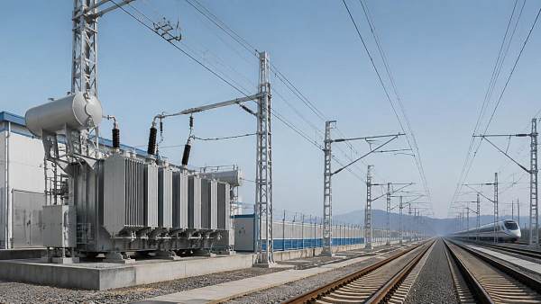
A traction power transformer should be sized from the electrical demand seen at the substation bus, not from the rated power of a single train. The practical starting point is to build a time-based load model for the route section supplied by the substation, then convert the resulting maximum demand, overload duty, power factor, harmonic content, voltage-drop limits, and redundancy requirements into transformer ratings and impedance requirements.
This becomes critical when a railway line appears adequately supplied on paper but experiences low catenary voltage during simultaneous acceleration, transformer overheating during dense service periods, or nuisance protection operations after a timetable change. In these situations, increasing the nameplate MVA alone may not solve the real issue. The selected traction power transformer must be evaluated as part of a system that includes the incoming grid, feeder arrangement, return circuit, rolling-stock behavior, and operating plan.
Start with the service pattern, not train nameplate power
A train may draw a very high power level while accelerating, but that demand is neither continuous nor necessarily coincident with the demand of other trains. Conversely, a line with moderate-power vehicles can produce a severe substation load where short headways, station spacing, gradients, and constrained dispatching cause several trains to accelerate within the same electrical section.
Begin by defining the electrical territory of the proposed substation. This should include the feeding arrangement, sectioning locations, adjacent substations, normal feed direction, and any contingency feed scenarios. A transformer that is acceptable with parallel feeding in normal operation may be insufficient when one neighboring supply point is unavailable and its section must be back-fed.
The load model should reflect actual operating states rather than an assumed average train load. At minimum, distinguish between:
- Acceleration after station stops, junction holds, or speed restrictions;
- Cruising demand at line speed;
- Auxiliary consumption for HVAC, compressors, lighting, controls, and onboard services;
- Coasting periods;
- Regenerative braking periods;
- Standing trains with auxiliaries energized;
- Degraded operating conditions, such as reduced headway recovery or single-track working.
For AC railways, the relevant values are commonly expressed as active power in MW, reactive power in MVAr, and apparent power in MVA. Transformer thermal sizing is tied principally to current and apparent power, while voltage regulation and network impact depend strongly on both active and reactive components.
Build a demand envelope from train movement
The most reliable approach is a load-flow or traction power simulation using route gradients, speed profiles, rolling-stock traction curves, station dwell times, timetable headways, feeder impedance, and substation topology. Where a full simulation is not yet available, a preliminary study can use a conservative diversity-based demand estimate, but the assumptions should be visible and traceable.
For each time interval, determine the combined power at the substation supply point:
Ptotal = ΣPtraction + ΣPauxiliary + Pnetwork losses
Reactive demand must then be included:
S = √(P² + Q²)
where S is apparent power, P is active power, and Q is reactive power. For a three-phase AC traction supply, line current can be estimated as:
I = S / (√3 × V)
where V is the relevant line-to-line voltage at the transformer secondary or supply bus.
These calculations should be made across the operating profile, not only at one selected peak. The evaluator needs at least three demand values: the highest short-duration peak, the highest sustained demand, and the expected demand under a credible contingency arrangement. A transformer may tolerate a short peak within its overload capability but still be unsuitable if that peak occurs repeatedly enough to raise winding hot-spot temperature beyond the intended duty.
Do not use average load as the primary rating basis
Average energy consumption is useful for utility billing and broad capacity planning, but it can conceal the demand events that determine transformer performance. A substation serving trains on a steep departure gradient may have a modest daily energy total while repeatedly seeing high current at the same points in the timetable. The thermal effect depends on load magnitude, duration, ambient conditions, cooling method, and the time available for the transformer to cool between peaks.
Conversely, applying the sum of every train’s maximum traction power without diversity can produce an unnecessarily oversized design. The right question is not “What is the total installed train power?” but “What combinations of train states can realistically occur inside this feeding zone, and how long do they persist?”
Separate normal capacity from contingency capacity
A major source of undersizing is treating normal operation as the sole design condition. Railway supply systems often need to maintain restricted service when a transformer, feeder, or adjacent substation is unavailable. The required level of continuity varies by route importance and operating philosophy, but the contingency case must be evaluated explicitly.
Where two transformers operate in parallel, their ratings, impedance values, vector groups, and tap positions must be compatible. A pair with substantially different impedance may not share load in proportion to nameplate rating. One unit can become overloaded while the other remains below its capacity, producing a misleading impression that total installed MVA is sufficient.
For a single-transformer installation, the decision is not simply whether the unit can carry the peak. It is whether the railway can accept the service consequence of losing that supply point, whether adjacent feeding can maintain voltage within vehicle limits, and whether scheduled operational restrictions are realistic during a fault or maintenance period.
Check voltage regulation before finalizing MVA
Transformer capacity and voltage quality are related but different constraints. A transformer can have enough thermal capacity while still allowing excessive voltage depression at the catenary or third-rail supply point during acceleration. The voltage seen by the train is influenced by source voltage, transformer tap setting, transformer impedance, busbar arrangement, feeder resistance and reactance, return-path impedance, and simultaneous train loading.
Transformer impedance deserves particular attention. Lower impedance generally reduces voltage drop through the transformer and can improve traction voltage during high demand. However, it also increases prospective short-circuit current, affecting switchgear duty, protection coordination, and earthing design. Higher impedance can limit fault current but may worsen voltage regulation. There is no universal “best” impedance percentage; it must be selected against the network study results.
Tap-changing capability should be considered as a voltage-management tool, not as a substitute for proper capacity or feeder design. Fixed taps may be suitable where the utility source is stable and the operating window is narrow. On-load tap changing may be justified where supply voltage varies materially and voltage must be maintained under changing demand. Its control logic should avoid excessive tap operations caused by fast traction-load fluctuations.
Use the correct voltage reference point
Checking only the transformer secondary bus can hide a problem at the far end of a feeder. The relevant limit is usually the voltage available to the rolling stock at its pantograph or collector interface, considering the worst credible train position. A demanding train may be electrically distant from the substation, with multiple trains between it and the source. That scenario can govern feeder reinforcement, substation spacing, transformer impedance, or the need for a revised sectioning strategy.
Account for power factor, harmonics, and unbalance
Modern traction converters can operate with improved power factor compared with older equipment, yet reactive demand should not be assumed away. The actual power factor during acceleration, low-speed operation, auxiliary loading, and regeneration should be obtained from the rolling-stock electrical data or validated simulation assumptions. A lower power factor raises current for the same MW demand and therefore consumes more transformer MVA capacity.
Harmonic currents require a separate assessment because they create additional losses in windings, structural parts, and connected equipment. The transformer should be evaluated for the expected harmonic spectrum of the traction fleet, including the possibility of mixed rolling stock during transition periods. A standard utility transformer design may not automatically suit a traction duty with significant converter-generated harmonics, rapid load variation, and frequent thermal cycling.
For single-phase railway electrification supplied from a three-phase utility system, phase balance is also a central issue. The selected transformer connection and network arrangement must address negative-sequence effects and the utility’s allowable unbalance conditions. A transformer rated adequately in MVA can still be unacceptable if the supply configuration creates excessive phase imbalance upstream.
Regenerative braking reduces energy, not always peak transformer duty
Regenerative braking is often credited as a direct reduction in substation capacity, but that conclusion is only valid when another load can absorb the returned energy at the same time. A braking train can supply accelerating trains in the same electrical section, reducing net demand at the transformer. If no receptive load is available, the energy may be rejected, limited by vehicle controls, absorbed by onboard resistors, or directed to an energy-storage or grid-export arrangement where such equipment exists.
Therefore, include regeneration as a time-coincident behavior in the load model rather than deducting a fixed percentage from traction demand. Also check reverse-power conditions where the network permits export toward the upstream system. Transformer, protection, metering, and utility-interface requirements may differ when bidirectional power flow is possible.
Translate the study into a transformer specification
Once the load and network calculations are complete, the transformer specification should state more than primary and secondary voltage plus MVA rating. Technical evaluation should normally capture the following items:
- Continuous rating at the defined ambient and cooling condition;
- Permitted cyclic and emergency overload duty, with the assumed load profile clearly stated;
- Primary and secondary voltage ranges, frequency, vector group, insulation levels, and neutral arrangement;
- Specified impedance and its permitted tolerance;
- Tap range, tap changer type where applicable, and voltage-control requirements;
- Harmonic loading assumptions and any required derating or enhanced thermal design;
- Short-circuit withstand capability consistent with calculated fault levels and clearing times;
- Parallel-operation requirements, including impedance matching and control interlocking;
- Cooling class, auxiliary supply needs, monitoring points, and alarm interfaces;
- Space, foundation, transport, fire-protection, and maintenance constraints at the substation.
The overload requirement should be written carefully. A generic request for “overload capability” is not enough because permissible loading depends on duration, starting oil and winding temperatures, ambient conditions, cooling availability, and expected repetition. Define the duty cycle that the transformer must survive rather than assuming every vendor interprets the requirement identically.
Leave room for expansion without buying unusable capacity
Future proofing should be based on identified changes: shorter headways, longer trains, new rolling stock, route extensions, additional branches, or anticipated changes in feeder configuration. It is often more practical to provide civil space, protection provisions, and switchgear bays for a future parallel transformer than to select one very large initial unit that operates lightly for years.
Light loading is not automatically harmless. It can affect efficiency, loss economics, cooling behavior, and the value of installed redundancy. The preferred arrangement depends on the expected growth path and on whether a second unit can be added without prolonged outages or major changes to the bus arrangement.
Before approving the final traction power transformer rating, reconcile the transformer thermal study with the traction load-flow results. The selected unit should pass the normal and contingency demand profiles, maintain acceptable rolling-stock voltage at the critical locations, remain within fault-duty constraints, and have a defined response to regeneration and harmonic loading. Treating those checks as one coordinated decision prevents the common mistake of selecting an MVA rating that looks sufficient on a schedule but fails under the operating conditions the railway will actually impose.
Recommended News
 Sep 29, 2026What drives traction systems price differences between rail projects?Traction systems price differences explained: compare duty cycles, voltage compatibility, integration, localization, and lifecycle costs for smarter rail procurement.
 Sep 26, 2026What to assess before selecting an electric traction system manufacturerChoose an electric traction system manufacturer with confidence. Explore key criteria for performance, reliability, safety, integration, energy efficiency, and lifecycle support.
 Sep 25, 2026When do full digitalization systems justify the investment?Full digitalization systems: discover when rail and maritime operators can turn connected data into safer operations, higher availability, and measurable ROI.
 Sep 23, 2026What drives automatic train control systems cost on rail projects?Automatic train control systems cost depends on integration, migration, safety testing, communications, and lifecycle support. Explore the key budget drivers for rail projects.
 Sep 21, 2026How to assess an ocean going vessel builder’s delivery riskAssess an ocean going vessel builder’s delivery risk with proven checks for schedules, capacity, design maturity, critical equipment, quality, and project controls.
 Sep 20, 2026What drives rail safety technology costs over a project lifecycle?Rail safety technology cost goes beyond equipment—explore lifecycle drivers from integration and safety assurance to cybersecurity, commissioning, and obsolescence.
 Sep 16, 2026What to verify before choosing an advanced ocean-going vessels supplierAdvanced ocean-going vessels supplier checklist: verify design authority, build quality, digital systems, delivery reliability, and lifecycle support before you buy.
 Sep 15, 2026What rail safety technology best reduces level-crossing risks in Southeast Asia?Rail safety technology Southeast Asia: discover how fail-safe signalling, barriers, obstacle detection and remote monitoring reduce level-crossing risks.
 Sep 14, 2026How exporters can reduce customs delays in global trade logisticsGlobal trade logistics for exporters: reduce customs delays with accurate data, clearance-ready documents, early filing, and proactive exception management.
 Sep 13, 2026When do global transportation network systems reduce delivery delays?Global transportation network systems reduce delivery delays by improving rail-port-vessel coordination, real-time visibility, and proactive decisions across complex land-sea supply chains.
 Sep 09, 2026When should you choose a rail and maritime manufacturer with dual-sector capability?Rail and maritime manufacturer guide: learn when dual-sector capability reduces integration risk, improves lifecycle support, and strengthens rail-to-port operations.
 Sep 08, 2026What to verify before selecting a railway signalling equipment supplierRailway signalling equipment supplier checklist: verify safety evidence, integration, cybersecurity, delivery capability, and lifecycle support before award.
 Sep 07, 2026How to size a traction power transformer for railway load demandTraction power transformer sizing guide: model railway load demand, peak duty, voltage regulation, harmonics, and contingency capacity for reliable service.
 Sep 07, 2026How do customization options for industrial connectors affect lead times?Customization options for industrial connectors can impact lead times, cost, and compliance. Learn how to specify smarter for rail and marine projects.
 Sep 05, 2026What information should an industrial sourcing guide include?Industrial sourcing information procurement guide: evaluate suppliers, compliance, lifecycle costs, interfaces, and lead times for smarter rail and maritime purchasing decisions.
 Sep 01, 2026How to find reliable maritime tender information before biddingMaritime tender information: learn how to verify sources, define bid-ready scopes, check qualifications, and reduce risk before submitting competitive marine bids.
 Aug 30, 2026How to select railway automation equipment for depots with phased upgradesRailway automation equipment for depots: learn how to plan phased upgrades that improve safety, throughput, integration, and lifecycle control.
 Aug 27, 2026How industrial sourcing intelligence pricing data supports budget approvalIndustrial sourcing intelligence pricing data helps teams benchmark scope, assess supplier risk, and build defensible budget approvals for complex rail and maritime assets.
 Aug 26, 2026When does a marine fuel efficiency solution make financial sense in the Middle East?Marine fuel efficiency solution Middle East: learn when retrofit savings, compliance value, and vessel data align to deliver credible ROI and smarter shipping investment decisions.
 Aug 24, 2026When does maritime automation for tankers deliver a real payback?Maritime automation for tankers delivers real payback when it cuts fuel use, reduces cargo risk, and improves uptime. See how owners can time investment for stronger ROI.
 Aug 23, 2026When do maritime logistics systems in the Middle East justify the costMaritime logistics systems Middle East: discover when rising delays, manual coordination, and poor visibility make system investment the smarter move for regional operators.
 Aug 22, 2026What drives vessel navigation system price for commercial fleetsVessel navigation system price depends on integration, compliance, automation, and support—not just hardware. Learn what drives fleet costs and compare quotes with confidence.
 Aug 21, 2026How to assess shipbuilding maritime tenders before biddingShipbuilding maritime tenders require more than price checks. Learn how to assess technical scope, compliance, supply chain, and commercial risk before bidding with confidence.
 Aug 20, 2026When does working with an ocean-going vessels distributor reduce supply risk?Ocean-going vessels distributor: learn when this partner cuts supply risk through stronger compliance, faster response, and better sourcing resilience in complex maritime procurement.