



Search News
Industry Portal
Popular Tags
When regenerative rail transit braking delivers meaningful energy savings
Author
Time
Click Count
When Regenerative Rail Transit Braking Delivers Meaningful Energy Savings
Regenerative rail transit braking can turn routine deceleration into a measurable energy-saving opportunity, but meaningful results depend on duty cycles, network receptivity, vehicle design, and control strategy. For a technical evaluation team, recovered energy cannot be judged from a headline regeneration-efficiency figure alone. The real question is whether that energy has a useful destination at the instant the train is braking.
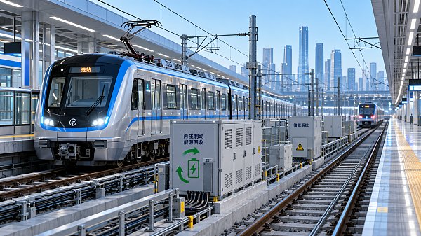
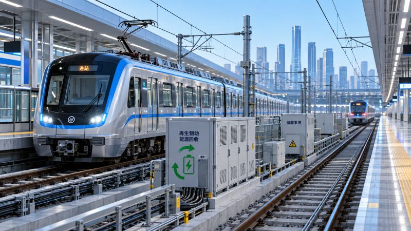
A metro train approaching a station carries substantial kinetic energy. In a conventional braking event, much of that energy is dissipated as heat through resistors and friction brakes. With regenerative braking, the traction motors operate as generators, converting kinetic energy into electrical power. That power may be used by another train accelerating nearby, absorbed by onboard or wayside storage, returned to the supply network where permitted, or rejected through braking resistors when no receiving path is available.
This distinction matters. A train may be technically capable of regeneration while a railway still captures only a modest share of the available energy. The gap is usually not a fault in the traction package. It is a system-level mismatch between when energy is produced, when it is needed, and what the electrical network can accept safely.
The first test: does the route create usable braking energy?
Regenerative rail transit braking is most attractive where trains repeatedly accelerate and decelerate at meaningful speed. Urban metro, light rail, airport rail, and suburban networks with close station spacing often create many regeneration events throughout the operating day. Frequent stops alone are not enough, however. A line with very short distances between stations may leave little time at higher speed, reducing the kinetic energy available during each braking cycle. Conversely, a route with wider spacing, steep gradients, or high operating speeds may offer stronger individual recovery opportunities.
Gradient deserves particular attention. A descending approach can extend the braking demand and raise recoverable energy, while an uphill approach may shorten it. Passenger loading also changes the calculation. A heavily loaded train has greater mass and therefore more kinetic energy at a given speed, but timetable variation, dwell time, adhesion limits, and comfort-oriented jerk limits all influence how consistently that theoretical energy can be recovered.
Intercity and high-speed operations can also benefit, but the result is less automatic. Long periods of steady cruising do not generate recoverable energy. The important events are terminal approaches, speed restrictions, gradients, and service-pattern changes. In these applications, braking control must be assessed alongside aerodynamic braking effects, friction-brake blending, wheel-slide protection, and the required stopping performance under degraded conditions.
Energy recovery depends on a receptive electrical system
The most economical destination for regenerated power is often another train drawing power on the same electrical section. One train brakes, another accelerates, and the traction supply transfers energy without adding a dedicated storage asset. This is why timetable structure and train density can affect energy performance as much as vehicle hardware.
In a busy metro corridor, overlapping acceleration and braking events may occur frequently. Yet even there, transfer is not guaranteed. The receiving train must be electrically connected in a way that permits the exchange, and the supply voltage must remain within the limits accepted by the traction and network protection systems. If the line voltage rises beyond the permitted threshold during braking, the train’s control system will reduce regeneration and transfer excess power to braking resistors.
On a lightly trafficked line, during off-peak operation, or near a terminal where few trains are accelerating, receptive load may be absent. That is the point at which a project should examine alternatives: reversible substations, wayside energy storage, onboard storage, or operational changes that improve the overlap between braking and acceleration. Each option solves a different constraint, and none should be selected before the actual voltage behavior and traction-load profile are understood.
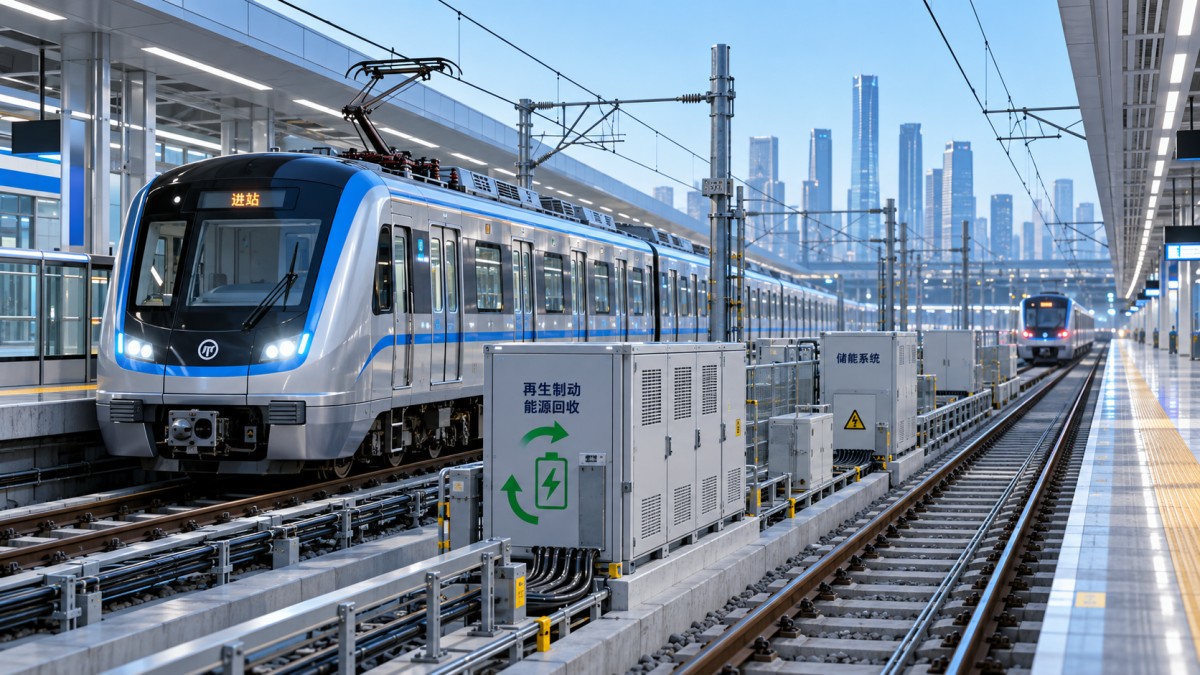
Four possible destinations for regenerated power
Why nominal regenerative efficiency is not the project result
Technical proposals often state traction-converter efficiency or the proportion of braking force that can be electrically generated. Those figures are relevant, but they are only part of the chain. An evaluation should separate at least three layers: energy available at the wheel-rail interface, electrical energy produced by the traction motors and converters, and energy ultimately reused rather than dissipated.
The usable result is affected by converter losses, motor operating range, auxiliary loads, line voltage, protection thresholds, storage losses, and the unavoidable role of friction braking at low speed. Adhesion conditions may impose further limits. In wet, contaminated, or low-adhesion conditions, wheel-slide protection and braking assurance take priority over maximizing regenerated energy. That is not a compromise in design quality; it is the correct safety hierarchy.
Thermal conditions also deserve closer scrutiny than they sometimes receive. If regeneration is frequently curtailed, resistor grids may see a higher duty than expected. Their cooling path, enclosure ventilation, environmental exposure, and diagnostic coverage must still support repeated braking events. Similarly, an energy-storage system should be evaluated at the expected ambient temperature, charge and discharge rate, and daily cycling profile—not only at a nominal laboratory condition.
Braking blending is where energy goals meet stopping assurance
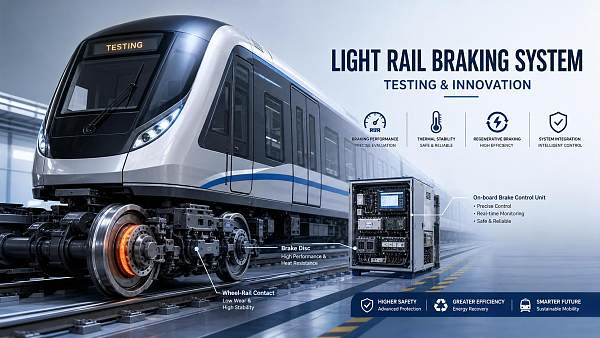
A rail vehicle does not choose between “regenerative braking” and “safe braking.” It blends electrical, rheostatic, pneumatic, and sometimes other braking functions to meet commanded deceleration while maintaining controllability. The braking control system must transition cleanly when line receptivity changes, a traction converter is unavailable, storage reaches its state-of-charge limit, or a wheel-slide event occurs.
This is especially important for technical evaluators reviewing retrofit concepts. Installing a storage device or modifying substation capability may improve energy capture, but it also changes the operating envelope seen by vehicle control, train protection interfaces, and electrical protection equipment. The study scope should include failure modes and degraded modes: loss of communications, failed cooling, sensor disagreement, unavailable storage, overvoltage response, and emergency braking behavior.
For modern automated railways, the link between signalling and traction behavior is increasingly relevant. Headway management, dwell-time regulation, and speed-profile optimization can alter the timing of acceleration and braking events. A more regular service pattern may improve opportunities for train-to-train energy exchange, but only if it does not undermine capacity, punctuality, passenger comfort, or the safety logic governing movement authority.
Choosing between storage, substations, and operational measures
Wayside storage is often considered when a particular traction-power section experiences repeated regenerative overvoltage but has insufficient nearby demand. It can absorb short, high-power pulses and later support acceleration, reducing peak demand as well as wasted braking energy. The practical question is not simply how much energy the device can hold. Its power capability, response time, state-of-charge management, cooling arrangement, maintainability, and end-of-life replacement plan may matter more than headline capacity.
Onboard storage can be justified where a vehicle must bridge non-electrified sections, limit power drawn at selected locations, or recover energy independently of local line receptivity. The penalties are also tangible: additional vehicle mass, integration complexity, packaging constraints, inspections, and condition monitoring. A design that works on a new-build train may be difficult to accommodate in an older fleet without affecting axle load, roof equipment layout, or maintenance access.
Reversible substations can offer a wider network-level path by allowing recovered energy to flow back toward the upstream alternating-current grid, subject to the characteristics of the supply architecture and local requirements. This route requires careful coordination with the utility and protection philosophy. It should never be treated as a plug-in answer, particularly where fault behavior, harmonic performance, or reverse-flow permissions require project-specific review.
Sometimes the least capital-intensive improvement is operational. Timetable adjustments, revised departure sequencing, speed-profile tuning, and better alignment of trains in adjacent sections may increase direct energy exchange. Such measures are not universally available, but they should be tested before a project assumes that hardware is the only solution.
A credible assessment begins with measured operating evidence
The strongest business case is built from synchronized evidence rather than broad assumptions. Train event data, traction and braking commands, line voltage, current, substation loading, timetable records, gradients, passenger-load assumptions, and ambient conditions can reveal where regenerated energy is actually lost. Data should cover representative operating states, including peak service, off-peak service, disruption recovery, seasonal weather variation where relevant, and different fleet configurations.
A useful evaluation model should identify each braking event, estimate the recoverable electrical energy, determine whether the line was receptive, and record curtailment or resistor-braking periods. It should then test candidate interventions against realistic control constraints. This makes it possible to distinguish a corridor-wide opportunity from a local bottleneck near one station, depot approach, or terminal.
Lifecycle evaluation should include more than energy value. Consider the maintenance burden of additional power electronics, storage replacement assumptions, spare-parts availability, diagnostic integration, cybersecurity exposure for connected monitoring systems, and the consequences of equipment outage. A solution that saves energy but creates recurring availability issues may not be attractive to an operator responsible for strict service commitments.
The questions that prevent a misleading conclusion
Before approving a regenerative braking enhancement, technical teams should be able to answer a few direct questions. How often does the fleet enter a braking regime that can generate useful power? What proportion of those events occurs when another load can receive it? At what voltage does regeneration begin to taper or stop? How much energy is being sent to resistor grids today? Are the observed conditions stable across service patterns? And if storage or reverse power flow is proposed, what changes are required in protection, thermal design, maintenance practice, and failure management?
These questions shift the discussion from a generic claim about “energy recovery” to an engineering decision about a specific railway. They also protect against an expensive but underused asset, such as storage that remains full during the periods when braking demand is highest or a reversible substation constrained by a utility interface that was not fully assessed.
At Global Transit & Ocean Tech, the analysis of rail braking sits alongside signalling architecture, traction power, pantograph performance, and wider transport-system intelligence. That perspective is useful because rail energy recovery is rarely isolated from the rest of the network. Vehicle braking logic, supply resilience, train spacing, maintenance conditions, and infrastructure investment priorities all shape the outcome.
Regenerative rail transit braking delivers meaningful savings when the railway can repeatedly convert braking energy into a usable electrical service without weakening safety, availability, or maintainability. The next step is usually not selecting a device. It is confirming the route’s braking profile, electrical receptivity, control limits, and lifecycle constraints with project-specific operating data.
Recommended News
 Oct 01, 2026When regenerative rail transit braking delivers meaningful energy savingsRegenerative rail transit braking can cut energy waste when routes, power systems, and controls align. Explore practical factors for measurable rail savings.
 Jul 17, 2026How to Evaluate Rail Transit Braking Systems for Light RailRail transit braking systems for light rail: learn how to evaluate response time, thermal stability, safety integration, and lifecycle cost for smarter, safer urban transit decisions.
![]() Jul 07, 2026Rail Transit Braking Systems in Southeast Asia: Key Upgrade RisksRail transit braking systems Southeast Asia face hidden upgrade risks beyond stopping power. Explore compatibility, heat, humidity, integration, and lifecycle factors before costly project decisions.
Jul 07, 2026Rail Transit Braking Systems in Southeast Asia: Key Upgrade RisksRail transit braking systems Southeast Asia face hidden upgrade risks beyond stopping power. Explore compatibility, heat, humidity, integration, and lifecycle factors before costly project decisions. Jul 02, 2026How to Compare a Rail Transit Braking Systems SupplierCompare a rail transit braking systems supplier by safety certification, braking performance, integration, delivery reliability, and lifecycle support to reduce project risk.
 Jun 25, 2026Rail Braking Equipment Failures: Common Causes and Fast FixesRail braking equipment failures can trigger delays and safety risks fast. Discover common causes, practical troubleshooting steps, and quick fixes to restore reliable braking.
 Jun 08, 2026Rail Transit Braking: Key Failure Points and Maintenance PrioritiesRail transit braking failures often start at pads, discs, valves, sensors, and control links. Learn key warning signs and maintenance priorities to improve safety, reliability, and fleet uptime.
 Jun 02, 2026Rail Transit Braking Performance Checks for Safer Daily OperationRail transit braking checks help improve safety, punctuality, and asset reliability. Learn key warning signs, inspection steps, and smarter daily operation practices.
 May 16, 2026Rail Transit Braking Performance Checks Before Fleet UpgradesRail transit braking checks before fleet upgrades reveal safety gaps, compatibility risks, and lifecycle costs—helping operators modernize with confidence, compliance, and fewer delays.